


11: Memory Peripheral Controller
GP4020 GPS Baseband Processor Design Manual 111
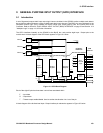
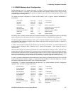
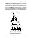
11.4 GP4020 Memory Area 3 Configuration
GP4020 Memory Area 3 is a special case where a number of internal components share resources with an
External chip select line – NSCS[2A]. The 12-channel correlator which resides in Memory Area 3 uses a re-timing
UIM interface, to retime data from Firefly speed (any frequency from the System Clock Generator (SCG)) to the
Correlator speed (nominally 40MHz).
The default hard-wired configuration at Reset of MPC Memory Area 3 (register address 0xE0008008) is
0xFF000034:
Access Waits bits [31:28] = ‘0y1111’ = 15 wait states
Stop Waits bits [27:24] = ‘0y1111’ = 15 wait states
Reserved bits [23:8] = ‘0x0000’
Configuration Mode bits [7:6] = ‘0y00’ (Mode 0 configuration)
Wait Control bit [5] = ‘1’ (enable MPC control of Wait-states)
Read Only Status bit [4] = '1' (Read Only enabled)
Sub Memory Write Status bit [3] = ‘0’ (Sub memory writes disabled)
Access Type bit [2] = ‘1’ (Memory access)
Data Size bits [1:0] = '0y00' (Byte (8-bit) wide)
As memory area 3 is used to access either the 12-channel correlator, Internal Peripheral Functions or NSCS[2A]
external chip-select line, the settings of the MPC must reflect the memory configuration that is being used.
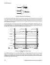
The dominant speed constraint in Memory Area 3 is the 12-channel correlator, which must have a 175ns access-
time specified in the configuration register. With a 20MHz firefly clock (50ns period) this equates to a minimum 4
wait-states in the Firefly clock.
In order to avoid complex re-configuring of the memory 3 area during code execution, it is recommended that any
external memory component used in Memory Area 3, should be slow-speed - 100ns access or slower is
recommended.
When the MPC changes its addressing from External to Internal destinations in Memory Area 3, there will be an
access delay at the point of first access of 1-wait-state, due to the way the data-bus I/Os are configured. However,
further accesses to the same part of the address space will NOT incur any further access delays apart from those
derived from accessing the correlator through the UIM interface. It is consequently recommended that "Start Write
Waits" and "Start Read Waits" be introduced when any externally accesses are required for Memory Area 3.
In order to guarantee reliable access to both external and internal memory components in Memory Area 3 when the
Firefly is being clocked at 20MHz or higher, it is recommended that a default of 3 Start-Wait States and 3 Access-
Wait-states are programmed into the MPC Area 3 Configuration register.
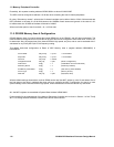
Consequently, it is strongly recommended that after boot-up of any system software, the MPC Configuration
register for Area 3 memory is configured as follows:
Start Write Waits bits [31:28] = ‘0y0011’ = 3 Start Waits
Access Write Waits bits [27:24] = ‘0y0011’ = 3 Access Waits
Stop Write Waits bits [23:20] = ‘0y0000’
Start Read Waits bits [19:16] = ‘0y0011’ = 3 Start Waits
Access Read Waits bits [15:12] = ‘0y0011’ = 3 Access Waits
Stop Read Waits bits [11: 8] = ‘0y0000’
Configuration bits [7:6] = ‘0y01’ (Mode 1 – Standard Mode)
Wait Control bit [5] = ‘1’ (enable MPC control of Wait-states)
Read Only Status bit [4] = '0' (Read Only NOT enabled)
Access Sub Memory Type bits [3:2] = ‘0y11’ (allows 8, 16 & 32-bit wide access)
Data Size bits [1:0] = '0y10' (32-bit wide)