


7: 12-Channel Correlator
88 GP4020 GPS Baseband Processor Design Manual
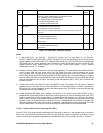
To get the SIGN and MAG count correctly into the accumulators, both the carrier and code mixers must be made
transparent.
The carrier mixing may be disabled by either:
(1) Setting CARRIER_MIX_DISABLE (bit 0 in SYSTEM_SETUP) to High to force a +1 on the Carrier DCO inputs
to all channels;
(2) If continued position finding is required from the other channels during the test, by setting CH5_ and
CH11_CARRIER_DCO_INCR to all 0’s, to give a constant level (zero frequency). This level should be set to a
known value by putting channels 5 and 11 briefly into the reset state (by using RESET_CONTROL register bits
6 and 12) during the time their Carrier DCO’s are programmed to zero frequency. This reset forces the phase
to all 0’s and hence the drives to the Prompt In–phase mixer to a fixed +1 and not a randomly selected –2, –1,
+1, or +2 that would result from just setting the frequency.
The C/A code mixing must be disabled by setting CODE_OFF/ONB (bits 11 in both CH5_ and CH11_SATCNTL) to
High. However, as the period of the count is set by the DUMPs from the Code Generator, the DCO clock to the
Code Generator must be set to the required frequency by programming the Code DCO, even though the code
output is disabled. A typical value is the frequency for the nominal code-chipping rate, so that the SIGN and MAG
counts are over a millisecond.
The results of monitoring the Front–end of the receiver may be used for fault diagnosis and for tuning the
parameters in the software for optimum satellite tracking with the particular Front–end or SIGN/MAG duty cycle.
To find the duty cycle of the SIGN signal, channel 5 is used. The In–phase accumulator CH5_I_PROMPT will add
+1 for each SIGN sample at High and will add –1 for each SIGN sample at Low. If the duty cycle is correct at 50%,
the sum will always be close to zero and only differ by the imbalance of sampling at the beginning and end of the
integration period.
The duty cycle may be calculated as follows:
SIGN duty cycle = R
S
= NSIGN1 / N = (N + ACC5) / 2N (nominally 0.50)
Where: N = Total No of samples in integration period.
NSIGN1 = Total No of samples for which SIGN was High.
NSIGN0 = Total No of samples for which SIGN was Low.
ACC5 = Total value in the CH5_I_PROMPT accumulator, as read after a DUMP.
N = N SIGN1 + N SIGN0
ACC5 = N SIGN1 – N SIGN0
To find the duty cycle of the MAG signal, channel 11 is used. The In–phase accumulator CH11_I_PROMPT will add
–3 for each MAG sample at High and will add –1 for each MAG sample at Low. If the duty cycle is correct (30%),
the sum will be: –1.6 * (Number of samples) plus an allowance for the imbalance of sampling at the beginning and
end of the integration period. The duty cycle may be calculated as follows:
MAG duty cycle, R
M
= NMAG3 / N = – (N + ACC11) / 2N (nominally 0.30).
Where: N = Total No of samples in integration period.
N MAG3= Total No of samples for which MAG was High
N MAG1= Total number of samples for which MAG was Low
ACC11 = Total value in the CH11_I_PROMPT accumulator, as read after a DUMP.
N = N MAG3 + N MAG1 ,
ACC11 = –3 * N MAG3 –N MAG1