


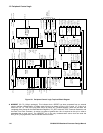
12: Peripheral Control Logic
122 GP4020 GPS Baseband Processor Design Manual
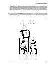
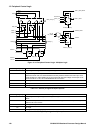
A single Interrupt line, PER_INT, is produced from 3 Peripheral Control Logic Interrupt signals from the Real Time
Clock (RTC_CMP_INT), the 1PPS Timemark Generator (TIC_INT), and the POWER_GOOD input (Pin 64 (100-pin
package)). The PER_INT interrupt is connected to the Firefly Interrupt Controller, and the signal which generated
PER_INT interrupt can be determined from the RTC_CMP_INT, POW_GD_INT and TIC_INT bits of the
PER_STAT register.
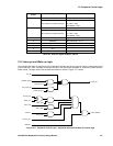
A wake-up event occurs when the NSLP_RESET internal reset line toggles from High to Low. GP4020 modules
that have been put to sleep can be awoken by a wake-up event. There are three sleep enable bits in the
POW_CNTL register, which are cleared by the NSLP_RESET signal at each Wake-up event:
1) F_SLEEP. When enabled, the BµILD Clock to the Firefly MF1 (and most of external BµILD bus modules) is
inhibited. The Watchdog and UART2 are NOT disabled by this action; they are sourced with the UART_CLK
signal, NOT BµILD Clock.
2) PLL_SLEEP. When enabled, the PLL in the System Clock Generator module is disabled.
3) RF_SLEEP. When enabled, the 40MHz Low Level Differential Input cell of the System Clock Generator is
disabled. In addition, if the DISCIO pin (Pin 55 (100-pin package)) is set by the Multiplex Logic (see earlier) to
connect to RF_SLEEP and RF_PD, the RF Front-end IC will also be disabled.
The Wake-up event can be created by any of the following scenarios:
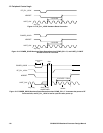
a) TIC_INT interrupt, from the 1PPS Timemark Generator. The TIC_INT can be programmed to occur at every
TIC; nominally once every 0.0999999s, or every time the 1PPS generator automatically extends a TIC period
by 175ns. This feature can be enabled / inhibited using TIC_INT_EN[1:0] in the PER_STAT register.
b) POWER_GOOD failure. This allows the full GP4020 chip to be re-awaken if a Power-supply failure has been
detected (only works effectively, if POWG_EN in POW_CNTL is set to '0'). This feature can be enabled /
inhibited using POW_INT_EN in the PER_STAT register.
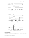
c) Real Time Clock interrupt (RTC_CMP_INT). The Real Time Clock can be set with a comparison value, which
when the accumulated time reaches the comparison value, the RTC_CMP_INT line goes High. Essentially, this
is a variable length wake-up timer facility, which allows blocks of the GP4020 to be put to sleep for any period
from between 30.5us and 256s. This feature can be enabled / inhibited using RCMP_INT_EN in the
PER_STAT register.
d) Accumulated Data Interrupt (ACCUM_INT) or Measurement Data Interrupt (MEAS_INT) from the 12-
channel Correlator. An ACCUM_INT interrupt is produced each time the correlator requires the microprocessor
to retrieve Accumulated GPS data from the Accumulation registers in each of the tracking modules. This is
nominally once every 505µs but can be adjusted using the PROG_ACCUM_INT register in the 12-channel
correlator to be between 175ns and 1.43ms. The MEAS_INT interrupt is a signal derived from the 12-channel
correlator TIC signal, and is nominally produced 50ms before each TIC. This feature can be enabled / inhibited
using WAK_COR in the POW_CNTL register.
e) UART_INT interrupt, caused by new external data being received by the UART2 Rx input (pin 77 (100-pin
package)). This feature can be enabled / inhibited using WAK_UART in the POW_CNTL register.
f) Discrete input interrupt (DISCIP1). When a High is detected on GPIO[4] (pin 95 (100-pin package)), this can
be used to produce a wake-up event. This feature can be enabled / inhibited using WAK_DISC in the
POW_CNTL register.
g) Watchdog interrupt (WATCH_INT), prior to a Watchdog time-out. The Watchdog produces two signals:
• WATCH_INT which is used to interrupt the microprocessor to instruct it to reset the watchdog;
• WATCH_TM, which is used to indicate that the Watchdog has interrupted the microprocessor for attention,
but the microprocessor has NOT responded.
When a WATCH_INT signal is produced (period of which is programmable within the Watchdog block), this
can be used to wake-up the microprocessor, if it is in sleep mode. The WATCH_INT wake-up event cannot be
disabled unless the watchdog itself is disabled, by clearing the WATCH_EN bit of the POW_CNTL register.