


10: Interrupt Controller
108 GP4020 GPS Baseband Processor Design Manual
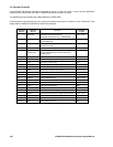
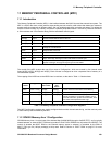
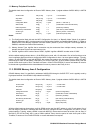
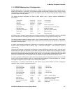
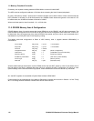
In the GP4020, the interrupt channels are allocated as shown in Table 10.2 below. In each case the application
software for the GPS receiver will need to configure the interrupt channels as shown.
The GP4020 Interrupt Controller has a Base Address of 0xE000 6000.
Further details for the programming of the Interrupt Controller can be found in Section 5 of the "Firefly MF1 Core
Design Manual" DM5003, available from Zarlink Semiconductor.
Interrupt
Channel
Interrupt
Source
Function
Level/Edge
Trigger
0 Watchdog Watchdog approaching time-out.
Watchdog requires reset key = 0xECD9F7BD
Level - Act HI
1Correlator
ACCUM_INT - interrupt to service GPS
Accumulation data
Level - Act HI
2 Correlator MEAS_INT - interrupt to service GPS
Measurement data
Level - Act HI
3 DMAC Channel status change Level - Act HI
4
Peripheral
Control Logic
Interrupt to service peripheral function. Function to
be serviced determined by read of PER_STAT
register in PCL.
Level - Act HI
5 N/A NOT USED. Tied to "0" N/A
6 TIC1 TIC source 1 Time out A Edge
7 TIC1 TIC source 1 Time out B Edge
8 RF_PLL_LOCK RF Front-end PLL is NOT locked Level - Act LO
9 to 12 N/A (NOT USED. Tied to "0") N/A
13 BSIO Serial Input / Output block interrupt Level - Act HI
14 UART1 Transmit / Receive error or modem status change Level - Act HI
15 UART1 Receive Buffer Full Level - Act HI
16 UART1 Transmit Buffer Empty Level - Act HI
17 N/A (NOT USED. Tied to "0")" N/A
18 TIC2 TIC source 2 Time out A Edge
19 TIC2 TIC source 2 Time out B Edge
20 IEXTINT2 External Interrupt needs service User defined
21 to 25 N/A (NOT USED. Tied to "0") N/A
26 UART2 Transmit / Receive error or modem status change Level - Act HI
27 UART2 Receive Buffer Full Level - Act HI
28 UART2 Transmit Buffer Empty Level - Act HI
29 to 31 N/A (NOT USED. Tied to "0") N/A
Table 10.2 GP4020 Interrupt Sources