


12: Peripheral Control Logic
130 GP4020 GPS Baseband Processor Design Manual
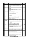
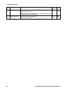
Bit
No.
Mnemonic Description Reset
Value
R/W
2 POW_RESET
(See Note 2)
'1' = Reset due to POWER_GOOD = Low, has occurred since last
CLR_RST or NSRESET clear-event.
‘0’ = No reset event due to POWER_GOOD has occurred
0R
1 WAT_RESET
(See Note 2)
'1' = Reset due to Watchdog Time-out, has occurred since last CLR_RST or
NSRESET clear-event.
‘0’ = No reset event due to Watchdog has occurred
0R
0 NSRST_RESET
(See Note 2)
'1' = Reset due to NSRESET (pin 75 (100-pin package)) = Low, has
occurred since last CLR_RST clear-event.
‘0’ = No reset event due to NSRESET has occurred
0R
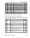
Table 12.8 PCL PER_STAT Register
Notes:
1) When PER_INT received from PCL, the software Interrupt Service Routine should read bits 10:8 to determine
which interrupt source has caused the interrupt to occur.
2) Bits 4:0 reset by setting CLR_RST ='0' or NSRESET='0' only. All other reset sources have no effect.