


7: 12-Channel Correlator
82 GP4020 GPS Baseband Processor Design Manual
Bit
No.
Mnemonic Description Reset
Value
R/W
15:12
Not Used
-W
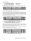
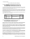
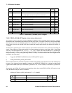
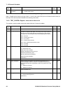
11 CH11_SELECT '1' = enables the Multi-channel write operations on Channel 11.
'0' = disables Multi-channel write operations on Channel 11.
0W
10 CH10_SELECT (as bit 11 but for channel 10) 0 W
9 CH9_SELECT (as bit 11 but for channel 9) 0 W
8 CH8_SELECT (as bit 11 but for channel 8) 0 W
7 CH7_SELECT (as bit 11 but for channel 7) 0 W
6 CH6_SELECT (as bit 11 but for channel 6) 0 W
5 CH5_SELECT (as bit 11 but for channel 5) 0 W
4 CH4_SELECT (as bit 11 but for channel 4) 0 W
3 CH3_SELECT (as bit 11 but for channel 3) 0 W
2 CH2_SELECT (as bit 11 but for channel 2) 0 W
1 CH1_SELECT (as bit 11 but for channel 1) 0 W
0 CH0_SELECT (as bit 11 but for channel 0) 0 W
Table 7.31 CORR MULTI_CHANNEL_SELECT Register
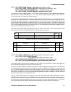
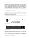
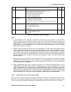
7.6.26 PROG_ACCUM_INT Register - Write Address Offset 0x1AC
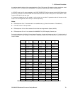
This register is used in conjunction with the INTERRUPT_PERIOD bit of the SYSTEM_SETUP register to configure
the period of the Accumulation Data Interrupt (ACCUM_INT) signal. This signal is used to tell the microprocessor
that it should check ALL the STATUS registers in the correlator, to see if there is any new Accumulation data. This
should occur once for every DUMP event, but normally the interrupt period should be shorter than DUMP (i.e.
<1.023ms).
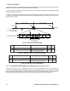
ACCUM_INT is generated by a 13-bit binary down counter which counts down to zero, producing an ACCUM_INT
output. It then loads to a Preset value stored in its Preset register and starts to count down again. If the Preset
value is P, the count sequence is P, P–1, P–2, ..., 1, 0, P, P–1. Hence, the counter divides by P+1, producing an
output with a period of (P+1) * clock period. Since the ACCUM_INT counter is clocked by the multi–phase clock,
the clock rate is (7 * clock period) (nominally 40MHz, i.e. 25ns). The value stored in the Preset register can be
modified in one of two ways:
i) Toggle the INTERRUPT_PERIOD bit of the SYSTEM_SETUP register,
ii) Writing to the PROG_ACCUM_INT location.
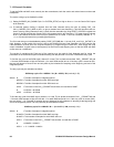
Either of these actions will overwrite the previous contents of the Preset value and either one or both methods may
be used. If the Interrupt Counter detects an edge on the INTERRUPT_PERIOD bit it will load into the Preset
register either 0x0B45 (505.05µs) if INTERRUPT_PERIOD is a '0', or 0x1313 (854µs) if INTERRUPT_PERIOD is a
'1'.
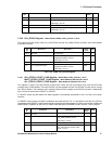
Alternatively, the ACCUM_INT counter may be loaded by writing direct to the PROG_ACCUM_INT location. In this
case, the new ACCUM_INT period is as follows:
ACCUM_INT Period = (PROG_ACCUM_INT + 1) * 7 /(40MHZ)
Bit
No.
Mnemonic Description Reset
Value
R/W
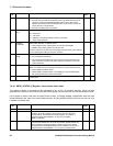
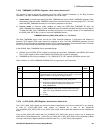
15:13
Not used
-W
12:0 ACCUM_INT[12:0] 13-bit ACCUM_INT down-count period value. 0x0B45 W
Table 7.32 CORR PROG_ACCUM_INT Register