


7: 12-Channel Correlator
GP4020 GPS Baseband Processor Design Manual 71
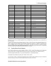
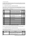
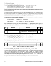
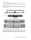
7.6.7 CHx_CARRIER_CYCLE_COUNTER Register - Offset <CHx_Control> + 0x08
MULTI_CARRIER_CYCLE_COUNTER Register - Offset (0x180 + 0x08)
ALL _CARRIER_CYCLE_COUNTER Register - Offset (0x1C0 + 0x08)
Bit
No.
Mnemonic Description
Reset
Value
R/W
15:0
Not used
Write–only in Test-mode only: Value loaded into lower 16-bits of
CHx_CARRIER_CYCLE_COUNTER along with zeros into the upper
4-bits.
((A write to these registers only has effect when in test mode (bit 3 of
TEST_CONTROL set High)).
0x0000 W
Table 7.10 CORR CHx_CARRIER_CYCLE_COUNTER Register
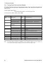
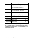
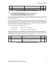
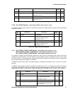
7.6.8 CHx_CARRIER_CYCLE_HIGH Register - Offset <CHx_Control> + 0x18
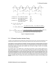
The Correlator tracking channel hardware allows for measurement of integrated carrier phase through the
CHx_CARRIER_CYCLE_HIGH and _LOW and the CHx_CARRIER_DCO_PHASE registers, which are part of the
Measurement Data sampled at every TIC. The CHx_CARRIER_CYCLE_HIGH and _LOW registers contain the 20-
bit number of positive going zero crossings of the Carrier DCO (4-bits are in _HIGH and 16-bits in _LOW). The
cycle fraction can be read from the CHx_CARRIER_DCO_PHASE register.
In the CHx_CARRIER_CYCLE counter, a TIC generates two consecutive actions. First it latches the four more
significant bits of the cycle counter into CHx_CARRIER_CYCLE_HIGH and the 16 less significant bits into
CHx_CARRIER_CYCLE_LOW. Then it resets the cycle counter.
After each TIC, every time the Carrier DCO accumulator generates an overflow because of a carrier cycle being
completed, the cycle counter increments by one.
The nominal CARRIER DCO frequency with no Doppler and no oscillator drift compensation is 1.405396825 MHz,
so in 100 ms, there will be about 140540 cycles.
In almost all applications, the number of Carrier DCO cycles does not vary much from one TIC interval to another. It
is possible to predict the Most Significant Bits of the value, and then only read the CHx_CARRIER_CYCLE_LOW
register.
CHx_CARRIER_CYCLE_HIGH and _LOW contents are not protected by an overwrite protection mechanism and
so must be read before the next TIC. For further information on the Carrier Cycle Counter, refer to Section 7.4
"Controlling the 12 Channel Correlator" on page 59.
Bit
No.
Mnemonic Description
Reset
Value
R/W
15:4
Not used
'0' when read 0 R
3:0 CHx_CARRIER_CYCLE [19:16] Bits 19:16 of the 20-bit Carrier Cycle Count 0000 R
Table 7.11 CORR CHx_CARRIER_CYCLE_HIGH Register
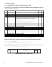
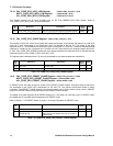
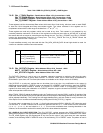
7.6.9 CHx_CARRIER_CYCLE_LOW Register - Offset <CHx_Control> + 0x08
The CHx_CARRIER_CYCLE_HIGH and LOW registers contain the 20-bit number of positive going zero crossings
of the Carrier DCO (4-bits are in HIGH and 16-bits in LOW). Refer to CHx_CARRIER_CYCLE_HIGH for more
information
Bit
No.
Mnemonic Description Reset
Value
R/W
15:0 CHx_CARRIER_CYCLE [15:0] Bits 15:0 of the 20-bit Carrier Cycle Count 0x0000 R
Table 7.12 CORR CHx_CARRIER_CYCLE_LOW Register