


6: BSIO Interface
GP4020 GPS Baseband Processor Design Manual 41
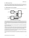
6.5 BSIO Interrupt Control
The Active High INT output is provided to allow the BSIO to operate in an interrupt driven environment. The five
interrupt sources are the WRREADY, RDREADY, WRITERR and READERR bits in the Status Register and a
derivative of OPERATION, OPCOMP to denote the current operation has completed. They will be enabled by
writing (Logic = High to enable) to their corresponding enable bits in the Interrupt Control Register.
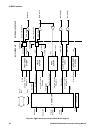
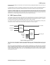
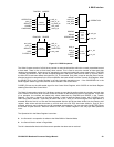
6.6 BSIO Write Buffer and Control Register
The Write Buffer consists of a two 32-bit transmit FIFO and a 32-bit transmit shift register and Control Logic as
shown in Figure 6.9 below.
FIFO
2 X 32 bits
TRFORMAT
SHIFT_TX
END_OF_TX
SDO
WRITERR
WRREADY
BuILD Bus
TXWORD
SELBYTE
TX_CLK
WFIFO_WR
MUX AND
SHIFT
CONTROL
WORD
REGISTER
BuILD Bus
CWORD_EN
CWORD_WR
32 bit bus
32 bit bus
Figure 6.9 BSIO Write Buffer and Control Register
Writing to the Read/Write Buffer loads the FIFO with a 32-bit word, whose valid bits will be shifted out serially via
the Transmit Shift Register. It should be borne in mind that not all the 32-bits would necessarily be sent since if byte
mode were selected by SELBYTE in the Transfer Register then they would be treated as four separate bytes to be
sent. However, if non-byte mode is selected then the TXWORD bits in the Transfer Register select the number of
bits in a word. Note that in this case the lower order bits make up the word, with the higher order ones being
redundant.
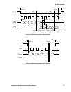
The Sequencer generates the signal TX_CLK, which forms the shift clock for serial data from the Shift Register,
with SHIFT_TX being the shift enable signal. It also asserts the END_OF_TX signal, after all the valid bits within a
32-bit Word have been shifted out.
WRREADY, a bit in the Status Register is set when the FIFO is ready to receive the next word, and is cleared when
the FIFO is full or when no more data is required to complete the current write operation. An Under-flow condition
i.e. a byte/word to be sent when the FIFO is empty, will result in the WRITERR bit in the Status Register being set
and the previous byte/word being sent. The WRITERR bit will be cleared by a read of the Status Register.
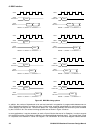
The TRFORMAT bits in the Slave Select Registers select between either a MSB or LSB first format (TRFORMAT =
High selecting MSB first) for each of the six slave devices. Note that in byte mode bit 7 of the byte would be the
MSB, whereas in word mode this would be its most significant bit.
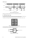
The internal output WFIFO_WR will be set when the first word in an Operation is written to the FIFO, and is cleared
at the end of an Operation. Whilst in Standard Mode, it will be used to set the OPERATION bit in the Status
Register.