


12: Peripheral Control Logic
GP4020 GPS Baseband Processor Design Manual 119
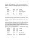
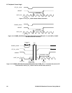
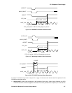
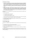
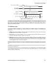
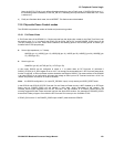
PLL_PD / PLL_SLEEP
PLL_IN_SEL
value change
NRESET
PLL_ENABLE
RTC_CLK
6 RTC_CLK cycles = 183us
<30.5us
....................... OR ........................
....................... OR ........................
Figure 12.9 PLL_ENABLE Timing
The selection of an external ROM in place of the Internal Boot ROM can also be determined during a reset. The
INT_NCS0 line will go High, and the Internal ROM will be selected, if EXT_NCS0 (IO_REV[9]) is set Low and
MULTI_FNIO pin is held High, whilst the NPOR_RESET line toggles from Low to High during a reset. If
MULTI_FNIO is held Low under the same scenario, the Internal ROM will NOT be selected after the reset, and the
state of EXT_NCS0 will be ignored.
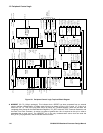
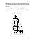
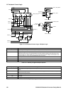
12.4 Multiplex Logic
The standard GP4020 is packaged in a 100-pin package. Ten additional signals can be accessed non-
simultaneously via some configurable Input / Output lines, as shown in Figure 12.10 below. The GP4020 pins that
allow this are:
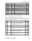
1) DISCIO (pin 55 (100-pin package)). This can be configured using the DISCIO_CFG[2:0] control lines from the
IO_REV register as shown in Table 12.1 on page 120.
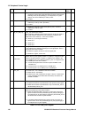
2) MULTI_FNIO (pin 54 (100-pin package)). This can be configured using the MFNIO_CFG[2:0] control lines,
from the IO_REV register as shown in Table 12.2 on page 120.
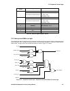
3) GPIO[7:0] (pins 91, 92, 93, 95, 96, 97, 99, 100 (100-pin package)). These can be configured using the
BSIO_MUX[1:0] and DISCOP_MUX control lines from the IO_REV register, and the UIM_TEST input control
line. Primarily used to interface to General Purpose Input Output (GPIO) cells, but can be multiplexed to BSIO
and other signals as shown in Table 12.3 on page 121.
All the pins indicated are tolerant to 5V input levels, so interfacing to an existing 5V-logic system is easy. The use of
the DISCOP and DISCIP1 lines from the 12-channel correlator allows access for test signals during manufacturing
test.
The DISCIP1 line can be also used as a discrete input, which can be read by the ACCUM_STATUS_B register in
the 12-channel correlator block.
The DISCOP line can also be used as a multi-function output line, as configured by the SYSTEM_SETUP register
in the 12-channel correlator block. It can be set to deliver either a CLK100KHz output from 12-channel correlator
block, or the RAW_Timemark signal.