


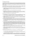

12: Peripheral Control Logic
GP4020 GPS Baseband Processor Design Manual 125
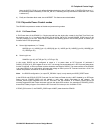
Address
Offset
Register Direction Function Function
Block
0x000 RTC_PRE Read Real Time Clock Pre-scaler value
RTC
0x002 RTC_SEC_B Read 16 LSBs of Real Time Clock second counter
RTC
0x004 COMP_RTCP Read /Write Comparison value for Real Time Clock Pre-scaler
RTC
0x006 COMPS_RTCS Read /Write Comparison value for 8 LSBs of Real Time Clock Second
counter, and 8 MSBs of Real Time Clock second counter
RTC
0x008 POW_CNTL Read /Write Power Control Register PCL
0x00A PLL_CNTL Read /Write PLL Control Register SCG
0x00C IO_REV Read /Write Input / Output Multiplex configure PCL
0x00E IP_READ Read Read access to Input / Output signals PCL
0x010 PER_STAT Read /Write Configure / monitor Interrupts and Resets PCL /
1PPS
0x012 TIC_RET Read /Write TIC Period slewing logic, and access a data retention
register.
1PPS
0x014 TIM_DEL_LO Read /Write Timemark Delay Down-Counter (LSBs)
1PPS
0x016 TIM_DEL_HI Read /Write Timemark Delay Down-Counter (MSBs)
1PPS
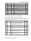
Table 12.4 Peripheral Control Logic Register Map
All registers are addressable as 32-bit locations only, but can use sub-memory access.
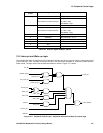
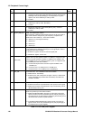
12.7.1 PCL Power Control Register - POW_CNTL - Memory Offset 0x008
This register is used to configure Power Control modes in the GP4020, and configure signal inputs and outputs for
the PLL in the System Clock Generator. This is primarily a write-only register, but on reading the register, the
settings made by the previous Write can be observed.
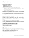
Bit
No.
Mnemonic Description Reset
Value
R/W
15 POWG_EN
Controls whether a power-fail indication due to POWER_GOOD input (Pin
64 (100-pin package)) should power-down the all GP4020 functions.
'1' = Disable all functions except the Real Time Clock, and the Data
Retention Register in the 1PPS Timemark Generator, when
POWER_GOOD = '0'
'0' = keep all functions enabled, irrespective of state of POWER_GOOD.
1R/W
14 WATCH_EN '1' = Enable Watchdog function at start-up.
'0' = Disable
0R/W
13 WAK_DISC Controls whether a sleep function previously enabled can be disabled by
setting a '1' on the DISCIP1 input (GPIO[4] pin 95 (100-pin package)),
from an external source.
'1' = Enable wake-up event due to DISCIP1 = High.
'0' = Disable.
0R/W
12 WAK_COR Controls whether a sleep function previously enabled can be disabled by a
correlator-sourced interrupt (ACCUM_INT or MEAS_INT).
'1' = Enable wake-up event due to correlator interrupt.
'0' = Disable.
0R/W
11 WAK_UART Controls whether a sleep function previously enabled can be disabled by
data received on the input of UART2.
'1' = Enable wake-up event due to UART2 received data.
'0' = Disable.
0R/W