


15: 1PPS Timemark Generator
GP4020 GPS Baseband Processor Design Manual 161
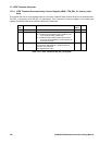
15.5.3 Timemark setting example 6 - Timemark Delay Counter with +0.5ppm Receiver Clock
Offset
In practice, the TIC period could be upto ±2.5ppm in error due to the Receiver Clock Offset (drift in the receiver
TCXO), which equates to approx. ±250ns in a TIC period of 0.0999999s. When a GPS receiver has acquired four
or more satellite signals, and has achieved a first fix, the receiver should be able to deduce the error in TIC period
due to Receiver Clock offset.
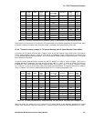
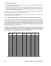
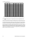
To take the timing example further, assume that the TIC period is in error by -50ns (+0.5ppm. PPM error is normally
equated to frequency, not time, and so the ppm sign is +, NOT -), giving an actual TIC period of 0.09999985s. This
means that the correction needed at each TIC to align to UTC, is +150ns, and consequently a delay of +1.5µs is
needed at the first Timemark, +3.0µs at the second time-mark, and the same increment will be added for each
Timemark event. If the calculated delay is greater than or equal to the period of 1 TIC, when the Counter delay can
be rolled over, and a TIC will be skipped by withholding the TIM_DEL register value. In this instance, the TIC skip
will occur once every 660,000 TICs (approx. every 18.5 hours), as shown in Table 15.6 below.
Timemark
Event (s)
TIC
Event
TIC Time (s) Required
delay (µs)
TIM_DE
L value
TIM_DEL
_LO
TIM_DEL
_HI
0 0 0 0 40000 0x9C40 0x40
1 10 0.9999985 1.5 40060 0x9C7C 0x40
2 20 1.999997 3 40120 0x9CB8 0x40
3 30 2.9999955 4.5 40180 0x9CF4 0x40
100 1000 99.999850 150 46000 0xB3B0 0x40
101 1010 100.9998485 151.5 46060 0xB3EC 0x40
425 4250 424.9993625 637.5 65500 0xFFDC 0x40
426 4260 425.999361 639 65560 0x0018 0x41
1000 10000 999.998500 1500 100000 0x86A0 0x41
1001 10010 1000.998499 1501.5 100060 0x86DC 0x41
10000 100000 9999.985000 15000 640000 0xC400 0x49
10001 100010 10000.9849985 15001.5 640060 0xC43C 0x49
66666 666660 66665.900001 99999 4039960 0xA518 0x7D
(SKIP TIC) 666670 66666.8999995 100000.5 4040020 0xA554 0x7D
66667 666671 66666.99999935 0.65 40026 0x9C5A 0x40
66668 666681 66667.99999785 2.15 40086 0x9C96 0x40
Table 15.6 TIC delay calculations for Timemark, using Delay Counter - TIC period with +0.5ppm error
15.5.4 Timemark setting example 7 - Timemark Delay Counter with +2.5ppm Receiver Clock
Offset
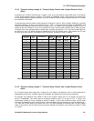
For TIC period errors which larger than +0.5ppm due to an offset in the Receiver clock, a similar technique for
adding delays to the RAW_Timemark signal can be applied, but skipped TICs will occur more frequently.
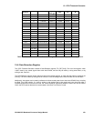
For example, if the Receiver Clock Offset is noted to be +2.5ppm (-250ns error on TIC period), the actual TIC
period is 0.09999965s. This means that the correction needed at each TIC to align to UTC, is +350ns, and
consequently a delay of +3.5µs is needed at the first Timemark, +7.0µs at the second time-mark, and the same
increment will be added for each Timemark event. If the calculated delay is greater than or equal to the period of 1
TIC, when the Counter delay can be rolled over, and a TIC will be skipped by withholding the TIM_DEL register
value. In this instance, the TIC skip will occur once every 285,000 TICs (approx. every 8 hours), as shown in Table
15.7 below.