


16: Up-Integration Module
GP4020 GPS Baseband Processor Design Manual 167
16 UP-INTEGRATION MODULE (UIM)
The GP4020 contains the Firefly MF1 core, within which is a Memory Peripheral Controller (MPC) which contains a
module called the Up Integration Module (UIM). Within the GP4020, the UIM is used to interface the Firefly MF1
core via the MPC to the following internal memory mapped components:
• 1PPS Timemark Generator
• 12-channel correlator
• Internal Boot ROM
• Internal RAM
• Peripheral Control Logic (PCL)
• Real Time Clock (RTC)
• System Clock Generator (SCG)
The UIM is designed to mimic the behaviour of the MPC external Input / Outputs; the only difference being that the
bi-directional sdata bus is split into 2 uni-directional buses.
The UIM is a sophisticated multiplexer and tristate control generator. It provides a link between the MPC port, the
SSM broadcast output, the internal Designer logic port and external IO’s. There is NO connection to the internal
BµILD Bus and consequently the UIM does not contain any internal registers.
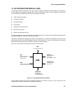
Figure 16.1 below shows how the UIM interacts with its environment.
UIM
SSM
MPC
DMA
DEVICE I/O
UIM SELECTS
UIM PORTS
Memory and peripheral
address, data and
control signals
External memory select
and flyby control (dack)
Test / External master bus
Designer Logic
Up integration port
(Inc. External masters)
Tie offs for internal
logic selection
Connections to/from
external pads.
(inc. all tri-state controls)
Figure 16.1 Up-Integration Module interfaces
Further details of the function of the Up-Integration Module can be found in Section 2 of the "Firefly MF1 Core
Design Manual" DM5003, available from Zarlink Semiconductor.