


7: 12-Channel Correlator
GP4020 GPS Baseband Processor Design Manual 53
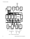
The individual sub–blocks in the tracking modules are:
7.2.1 Carrier DCO
The Carrier DCO, which is clocked at the SAMPCLK frequency, is used to synthesise the digital Local Oscillator
signal required to bring the input signal to baseband in the mixer block. It must be adjusted away from its nominal
value to allow for Doppler shift and reference frequency error.
When used with the GP2015/GP2010 the nominal frequency of this signal is 1.405396825 MHz (with a resolution of
42.57475 MHz) and is set by loading the 26-bit register CHx_CARRIER_DCO_INCR. This very fine resolution is
needed so that the DCO will stay in phase with the satellite signal for an adequate time.
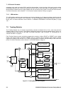
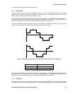
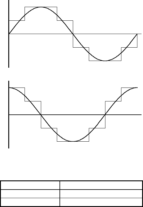
The Carrier DCO Phase cannot be directly set, but must be adjusted by altering the frequency. The Carrier DCO
outputs are 4 level, 8 phase sinusoids with the following sequences over one cycle:
Q
I
+2
+1
-1
-2
+2
-1
-2
+1
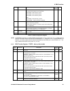
Figure 7.3 Waveform outputs from Carrier DCO I & Q LO (sinewaves are a guide only)
Destination Arm Sequence
I
LO
-1 +1 +2 +2 +1 -1 -2 -2
Q
LO
+2 +2 +1 -1 -2 -2 -1 +1
Table 7.1 12-channel Correlator Carrier DCO outputs
As the clock to the DCO is normally less than 8 times the output frequency, not all phases are generated in every
cycle. With a typical clock frequency of 5.714 MHz and an output frequency of 1.405 MHz, there are only approx. 4
phases per cycle. These will slide through the cycle as time progresses to cover all values.
7.2.2 Code DCO
The Code DCO is similar to the Carrier DCO block. It is also clocked at the SAMPCLK frequency, and synthesises
the oscillator required to drive the code generator at twice the required chipping rate. The nominal frequency of the