


7: 12-Channel Correlator
GP4020 GPS Baseband Processor Design Manual 61
For the polled method, the ACCUM_STATUS_A register is always read following every ACCUM_INT. In addition,
the ACCUM_STATUS_B register is read on each ACCUM_INT to ensure no Accumulated Data has been missed
and to check the TIC bit (along with several other status bits). The software tests the TIC bit to determine if new
Measurement Data is available to be read.
7.4.9 PRESET Mode
Each channel can be programmed into PRESET mode by writing a High into the PRESET/UPDATEB bit of the
CHx_SATCNTL register.
When a TIC occurs, the satellite code, epoch value and slew numbers are loaded, and a new phase programmed
into the Code DCO regardless of its previous value. Prior to the TIC, the channel operates with its previous
settings.
PRESET Mode has no effect on the Carrier DCO and Carrier Cycle Counter.
If PRESET mode is initiated, it should be allowed to operate to completion. The required sequence of operations is
as follows:
1) Write into CHx_SATCNTL to select the PRESET mode, together with the appropriate new settings.
2) Load the Code and Carrier DCO increment values. Note: These will take effect immediately thereby influencing
the current measurements.
3) Load the following Registers: CHx_CODE_DCO_PHASE, CHx_CODE_SLEW and
CHx_EPOCH_COUNT_LOAD. It is important that the CHx_EPOCH_COUNT_LOAD occurs last, because it
enables the PRESET operation on the next TIC.
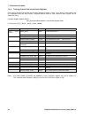
7.4.10 Interrupts
There are two interrupt sources: ACCUM_INT and MEAS_INT. Their sense is dependent upon the selected
microprocessor interface mode. The default ACCUM_INT period is 505.05µs. However, it can be reconfigured via
the PROG_ACCUM_INT register or by changing the INTERRUPT_PERIOD or FRONT_END_MODE bits in the
SYSTEM_SETUP register. The default MEAS_INT period is 50ms. However, this can be reconfigured via the
PROG_TIC_HIGH and PROG_TIC_LOW registers. Both ACCUM_INT and MEAS_INT are applied to the Interrupt
Controller (INTC) in the Firefly MF1, and can hence be enabled or disabled from there.
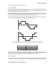
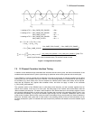
7.4.11 Signal Path Delay Introduced by Hardware Signal Processing
When it is desired to generate an accurate time reference from GPS signals or to time–stamp position fixes the
delays in the receiver must be allowed for. The signal path delay has two components, an Analogue path delay that
varies with temperature and component tolerances; and a Digital path delay that is constant if oscillator drift
variations are neglected.
The Digital delay is easier to estimate and is made up of the following:
i. The time from the sampling edge of the SIGN and MAG bits in the front end (SAMPCLK) to the re–sampling
in the Sample Latch. This is 175ns, less the propagation delay of SAMPCLK to the Front–end, giving approx.
125ns (including the delay in the series 1.5kΩ resistor in the SAMPCLK feed).
ii. Plus the time for the correlation in the Correlator on these same SIGN and MAG bits (125ns).
iii. Plus the delay in the accumulator to latch the sampled data (175ns ).
iv. Less the time between the correlation and the TIC clock phase that is before the accumulator latch phase
(75ns).
This gives a total Signal path delay of 400ns, less the SAMPCLK delay.