


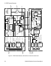


15: 1PPS Timemark Generator
158 GP4020 GPS Baseband Processor Design Manual
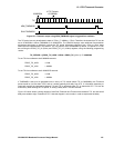
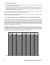
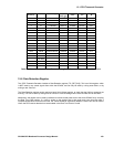
15.4.5 Timemark setting example 3 - TIC period Slewing with +2.5ppm Receiver Clock Offset
For TIC period errors which are larger than +0.75ppm due to an offset in the Receiver clock, it will be necessary for
the receiver to adjust the TIC period to be longer, using the PROG_TIC_HIGH and PROG_TIC_LOW registers.
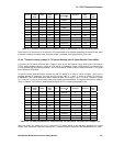
For example, if the receiver clock offset is noted to be +2.5ppm (-250ns error on TIC period), it is possible to
increment the value on PROG_TIC_LOW by 1 from 0xB823 to 0xB824, to set the supposed TIC period to be
0.100000075s. The actual TIC period will be 250ns less than this, at 0.099999825s. With this setting, the correction
needed at each TIC to align to UTC, is +175ns. Therefore, at each TIC, a value of '111' (seven M_CLK cycles)
needs to be added to the phase-offset. The process would occur, as shown in Table 15.3 below. TIC Event 0 is
assumed phase-aligned to UTC, so the required delay is 0µs.
TIC
Event
TIC_
CORR
[2:0]
Phase
Offset
Offset
delay
(ns)
Over
flow
Next TIC
Period (µs)
Cumulated
Overflow
Overflow
delay (ns)
Total
Delay
(ns)
0 111 0 0 0 99999.825 0 0 0
1 111 0 0 1 100000 1 175 175
2 111 0 0 1 100000 2 350 350
3 111 0 0 1 100000 3 525 525
4 111 0 0 1 100000 4 700 700
5 111 0 0 1 100000 5 875 875
6 111 0 0 1 100000 6 1050 1050
7 111 0 0 1 100000 7 1225 1225
8 111 0 0 1 100000 8 1400 1400
9 111 0 0 1 100000 9 1575 1575
10 111 0 0 1 100000 10 1750 1750
Table 15.3 TIC delay calculations for Timemark using TIC period slew, TIC period with +2.5ppm error
All the TIC events will need to adjust the TIC period. If the Receiver Clock offset appears larger still than +2.5ppm,
the TIC period will need to be further extended by a further data increment of the PROG_TIC_LOW register.
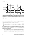
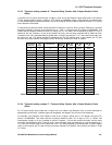
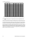
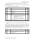
15.4.6 Timemark setting example 4 - TIC period Slewing with -2.5ppm Receiver Clock Offset
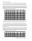
In order to show the opposite end of the Receiver Clock Tolerance limit, this example indicates what to do in order
to keep Timemark at 1PPS, when the Receiver Clock Offset means that TIC is longer than 100ms in length. For
TIC period errors which are larger than -1.00ppm due to an offset in the Receiver clock, it will be necessary for the
receiver to adjust the TIC period to be shorter than the default value, using the PROG_TIC_HIGH and
PROG_TIC_LOW registers.
For example, if the receiver clock offset is noted to be -2.5ppm (+250ns error on TIC period), it is possible to
decrement the value on PROG_TIC_LOW by 1 from 0xB823 to 0xB822, to set the supposed TIC period to be
0.099999725s. The actual TIC period will be 250ns greater than this, at 0.099999975s. With this setting, the
correction needed at each TIC to align to UTC, is +25ns. Therefore, at each TIC, a value of '001' (seven M_CLK
cycles) needs to be added to the phase-offset. The process would occur, as shown in Table 15.4 below. TIC Event
0 is assumed phase-aligned to UTC, so the required delay is 0µs.
TIC
Event
TIC_
CORR
[2:0]
Phase
Offset
Offset
delay
(ns)
Over
flow
Next TIC
Period (µs)
Cumulated
Overflow
Overflow
delay (ns)
Total
Delay
(ns)
0 001 0 0 0 99999.975 0 0 0
1 001 1 25 0 99999.975 0 0 25
2 001 2 50 0 99999.975 0 0 50
3 001 3 75 0 99999.975 0 0 75
4 001 4 100 0 99999.975 0 0 100