


18: Watchdog Timer
176 GP4020 GPS Baseband Processor Design Manual
18 WATCHDOG TIMER (WDOG)
The function of the Watchdog Timer block [WDOG] is to detect hardware or run-time software errors. It performs
this function by requiring the processor to write to one of its registers periodically. Should this not occur, the
Watchdog will time-out and reset the system. This ensures that hardware/software lock-ups are recoverable. A
watchdog timer exists on the BµILD bus to verify that the ARM
®
code is always in a known state. A value must be
written to the timer within a programmed period to avoid an interrupt being sent to the ARM7TDMI processor. The
Watchdog timer is disabled by default by a chip reset, but can be enabled by setting WATCH_EN (Bit 14 of the
POW_CTRL register in the PCL block) to a Logic '1'. Either a time-out failure signal is triggered by the 8-bit timer
expiring, or a register bit set to raise the signal. In either case this signal is intended to shut off the GP4020 in order
to reset it.
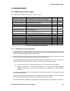
The watchdog timer contains a 32-bit counter and an 8-bit counter. Each of the counters has programmable load
values. A 32-bit (primary) counter counts down until either it reaches zero or a fixed value is written to the watchdog
control register. On expiration, an interrupt is sent to the ARM7TDMI to notify it of Watchdog expiration and the
secondary 8-bit counter begins counting down.
If the watchdog is not written to by the time the 8-bit counter counts down, the ASIC is reset. The primary counter is
clocked directly from the Firefly MF1 Subsystem clock (UART_CLK). The secondary counter is clocked by
UART_CLK after passing through a divide-by-sixteen pre-scaler.
The watchdog timer generates periodic interrupts (WATCH_INT) to the ARM7TDMI processor, which can also be
monitored within the Peripheral Control Logic block, to allow system wake-up to occur at the time of an interrupt.
Should the processor not respond to the interrupt within a certain time a secondary counter times out and triggers
the Peripheral Control Logic to provide a system-wide reset via the NPOR_RESET and NRESET lines.
To respond, the processor needs to write a specific, predefined value into the restart register. This "key" is
necessary to guard against errant software accidentally restarting the watchdog, since it is extremely unlikely that it
would write the correct 32-bit number into the watchdog restart register. The WDOG output is reset via the external
NSRESET signal.
18.1 Design Features
The main features of this watchdog timer are:
• “Key” mechanism for restarting the watchdog prevents accidental restarts
• Adjustable interrupt frequency
• Adjustable time-out delay
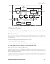
A Block diagram of the GP4020 Watchdog is shown in Figure 18.1 below.