


APPENDIX 17-7
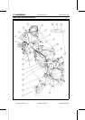
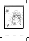
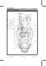
Cable, Wire, and Hose Routing
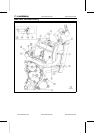
1. Right Headlight Connector
2. Right City Light Connector
3. Right Turn Signal Light Connector
4. Right Switch Housing Lead
5. Clamp the right switch housing lead.
6. Horn
7. Engine Subharness Joint Connector (To the Throttle Assy)
8. Inlet Air Temperature Sensor (To the Air Cleaner Box)
9. Starter Relay
10. Frame Ground Lead
11. Regulator/Rectifier
12. Rear Brake Light Switch Lead
13. Battery Positive (+) Terminal
14. Battery Negative (–) Terminal
15. Clamp the fuel pump lead connector to the bracket.
16. Heat Pad
17. Starter Relay Lead
18. Front Frame
19. Rear Frame
20. Install the heat pad aligned with the bolt.
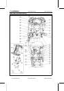
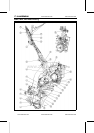
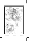
21. Viewed Left Side
22. Front
23. Battery Negative (–) Lead Connector
24. Alternator Lead
25. Engine Subharness Joint Connector
26. Clamp (The clamp attached on the main harness.)
27. Camshaft P osition Sensor Connector
28. Joint Connector for the stick coil and air switching valve leads (Install it into the bracket.)
29. Clamp (The clamp attached on the main harness.)
30. Immobilizer Amplifier
31. Left Switch Housing Lead
32. Ignition Switch Lead
33. Clamp the left switch housing lead and ignition switch lead.
34. Main Harness
35. Left Headlight Connector
36. Left City Light Connector
37. Meter Connector
38. Rear Brake Light Switch Lead Connector
39. Gray
40. Black
41. Through the harnesses into the rib of the center inner fairing.
www.zxforums.com
www.zxforums.com
www.zxforums.com
www.zxforums.com
www.zxforums.com
www.zxforums.com
www.zxforums.com