3-100 FUEL SYSTEM (DFI)
Oxygen Sensor Heaters (#1 and/or #2: Service Code 67) - Europe Models
If he tester reading is specified, check the power source
voltage Inspection.
NOTE
○
Be sure the battery is fully charged.
•
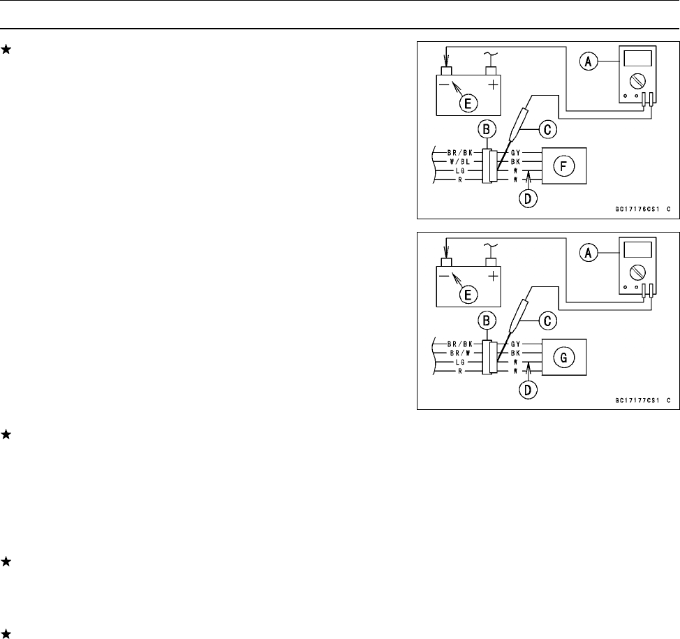
Connect a digital meter [A] to each oxygen sensor con-
nector [B], using the needle adapter [C].
Special Tool - Needle Adapter Set: 57001-1457
Oxygen Sensor Heaters Power Source Voltage
Connections to Oxygen Sensor Connector
Tester (+ ) → W (m ain harness side LG) lead [D]
Te ster (−) → Battery (−)Terminal[E]
Oxygen Sensor #1 [F]
Oxygen Sensor #2 [G]
•
Measure the power source voltage with the engine
stopped, and with the oxygen sensor connector joined.
•
Turn the ignition switch ON.
Power Source Voltage at Sensor Connector
Standard:
Battery Volta g e
If the reading is incorrect, check the following.
Battery (see Charging Condition Inspection in the Elec-
trical System chapter)
Main Fuse 30 A (see Fuse Inspection in the Electrical
System chapter)
Oxygen Sensor Heater Fuse 10 A (see Fuse Inspection
in the Electrical System chapter)
If the reading is good, the power source voltage is nor-
mal, Inspect the Red lead between the oxygen sensor
connector and the ECU for continuity, using the follow-
ing diagram.
If the wiring is good, inspect the ECU for its ground, and
power supply (see ECU Power Supply Inspection). If the
ground and power supply are good, replace the ECU (see
ECU section).
•
Remove the needle adapter set, and apply silicone
sealant to the connector for water proofing.
Sealant - Kawasaki Bond (Silicone Sealant): 56019-120
www.zxforums.com
www.zxforums.com
www.zxforums.com
www.zxforums.com
www.zxforums.com
www.zxforums.com
www.zxforums.com


