


ELECTRICAL SYSTEM 16-105
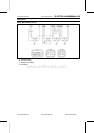
Switches and Sensors
•
Remove:
Fuel Tank (see Fuel Tank Removal in the Fuel Tank Re-
moval in the Fuel System (DFI) chapter)
Air Cleaner Housing (see Air Cleaner Housing Removal
in the Fuel System (DFI) chapter)
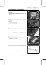
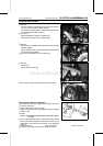
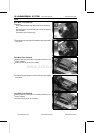
•
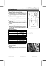
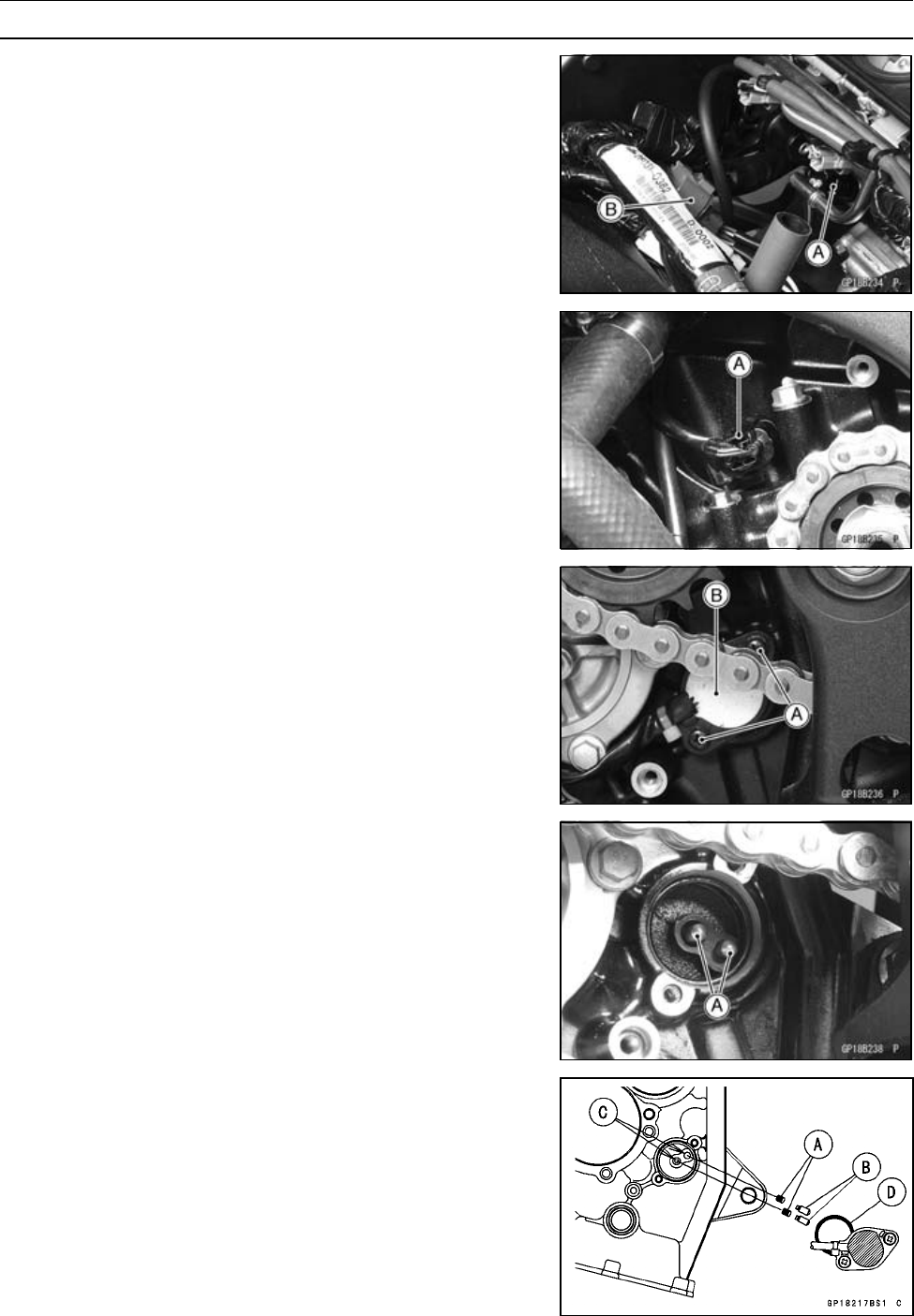
Disconnect:
Water Temperature Sensor Connector [A]
Gear Position Switch Lead Connector [B]
•
Remove:
Water Pump (see Water Pump Removal in the Cooling
System chapter)
Engine Sprocket Cover (see Engine Sprocket Removal
in the F inal Drive chapter)
•
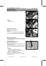
Disconnect the speed sensor connector [A].
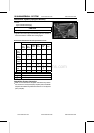
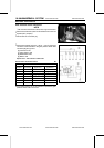
•
Remove:
Screws [A]
Gear Position Switch [B]
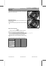
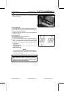
•
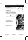
Remove the pins [A] and springs from the shift drum.
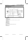
Gear Position Switch Installation
•
Securely place the springs [A] and pins [B] i nto the holes
[C]oftheshiftdrum.
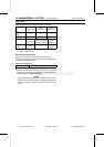
•
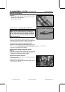
Apply grease to the new O-ring [D].
•
Apply a non-permanent locking agent to the gear position
switch screws.
•
Tighten:
Torque - Gear Position Switch Screws: 3.0 N·m (0.31 kgf·m,
27 in·lb)
•
Run the gear position s witch, oil pressure switch, speed
sensor and water temperature switch lead correctly (see
Cable, Wire, and Hose Routing section in the Appendix
chapter).
•
Install the removed parts (see appropriate chapters).
www.zxforums.com
www.zxforums.com
www.zxforums.com
www.zxforums.com
www.zxforums.com
www.zxforums.com
www.zxforums.com