


3-120 FUEL SYSTEM (DFI)
Fuel Injectors
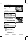
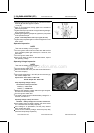
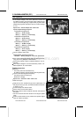
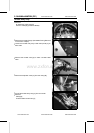
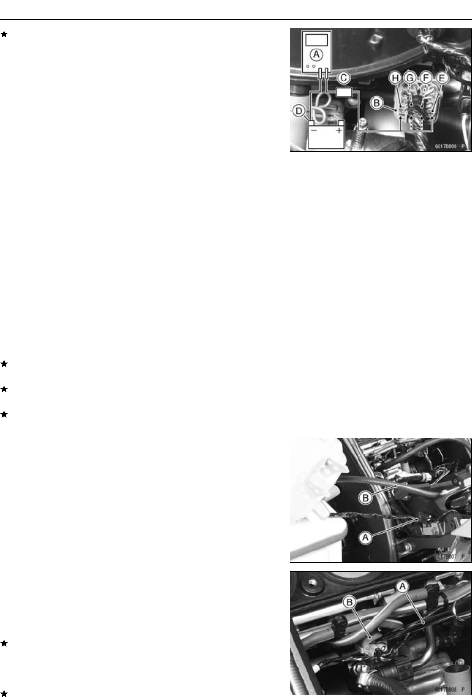
If the output voltage is out of the standard, remove the
air cleaner housing, and check the output voltage at the
injector connector [B] using a digital meter [A] and needle
adapter set [C] (when the lead is open, the output voltage
is 0 V).
Special Tool - Needle Adapter Set: 57001-1457
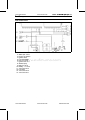
Injector Output Voltage at Injector
Connections to Injector #1
Meter (+) → BL/R lead [E]
Meter (–) → Battery (–) Terminal [D]
Connections to Injector #2
Meter (+) → BL/G lead [F]
Meter (–) → Battery (–) Terminal [D]
Connections to Injector #3
Meter (+) → BL/BK lead [G]
Meter (–) → Battery (–) Terminal [D]
Connections to Injector #4
Meter (+) → BL/Y lead [H]
Meter (–) → Battery (–) Terminal [D]
•
Turn the ignition switch ON.
Output Voltage at Injector Connector
Standard: Battery Voltage for 4 seconds, and then 0 V
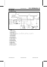
If the output voltage is normal, check the wiring for conti-
nuity (see wiring diagram in this section).
If the wiring is good, perform “Audible Inspection” for con-
firmation.
If the output voltage is out of the standard, perform “Au-
dible Inspection” for confirmation.
Audible Inspection
•
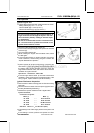
Remove:
Fuel Tank (see Fuel Tank Removal)
Air Cleaner Housing (see Air Cleaner Housing Removal)
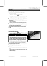
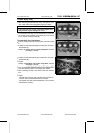
•
Connect the following parts temporary.
Fuel Pump Lead Connector [A]
Extension Tube [B]
Special Tool - Extension Tube: 57001-1578
•
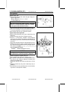
Start the engine.
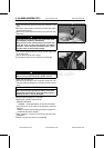
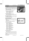
•
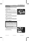
Apply the tip of a screwdriver [A] to the injector [B]. Put
the grip end onto your ear, and listen whether the i njector
is clicking or not.
•
A sound scope can also be used.
•
Do the same for the other injector.
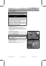
If all the injectors click at a regular intervals, the injectors
are good.
○
The click interval becomes shorter as the engine speed
rises.
If either injector doesn’t click, perform the “Injector Signal
Test” for injector operation.
www.zxforums.com
www.zxforums.com
www.zxforums.com
www.zxforums.com
www.zxforums.com
www.zxforums.com
www.zxforums.com