


PERIODIC MAINTENANCE 2-19
Maintenance Procedure
•
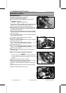
Back out the same number of turns counted when first
turned in. This is to set the screw to its original position.
NOTE
○
A throttle body has different “turns out” of the bypass
screw for each individual unit. On setting the bypass
screw, use the “turns out” determined during disassem-
bly.
•
Repeat the same procedure for other bypass screws.
•
Repeat the synchronization.
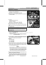
If the vacuums are correct, check the output voltage of
the main throttle sensor (see Output Voltage Inspection of
Main Throttle Sensor in the Fuel System (DFI) chapter).
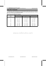
Main Throttle Sensor Output Voltage
Connections to ECU
Meter (+) → Y/W lead (terminal 26)
Meter (–) → BR/BK lead (terminal 34)
Standard: DC 0.65 ∼ 0.67 V (at idle throttle opening)
If the output voltage is out of the range, check the input
voltage of the main throttle sensor (see Input Voltage In-
spection in the Main Throttle Sensor section in the Fuel
System (DFI) chapter).
•
Remove the vacuum gauge hoses and install the rubber
caps on the original position.
•
For the California Model, install the vacuum hoses.
○
Route the vacuum hoses according to Cable, Wire, and
Hose Routing section in the Appendix chapter.
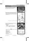
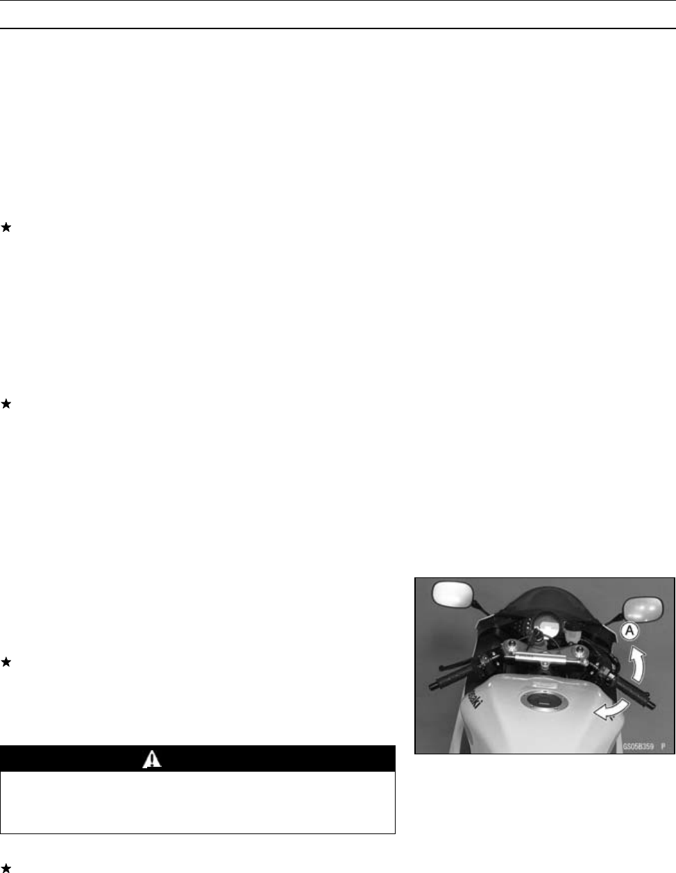
Idle Speed Inspection
•
Start the engine and warm it up thoroughly.
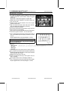
•
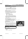
With the engine idling, turn the handlebar to both sides
[A].
If handlebar movement changes the idle speed, the
throttle cables may be improperly adjusted or incorrectly
routed, or damaged. Be sure to correct any of these
conditions before riding (see Cable, Wire, and Hose
Routing section in the Appendix chapter).
WARNING
Operation with improperly adjusted, incorrectly
routed, or damaged cables could result in an un-
safe riding condition.
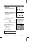
•
Check the idle speed.
If the idle speed is out of specified range, adjust it.
Idle Speed
Standard: 1 100 ±50 r/min (rpm)
www.zxforums.com
www.zxforums.com
www.zxforums.com
www.zxforums.com
www.zxforums.com
www.zxforums.com
www.zxforums.com