


16-34 ELECTRICAL SYSTEM
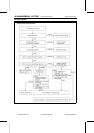
Charging System
•
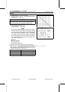
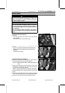
To check the alternator output voltage, do the following
procedures.
○
Turn off the ignition switch.
○
Remove the fuel tank (see Fuel Tank Removal in the Fuel
System (DFI) c hapter).
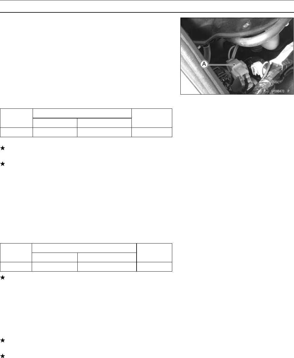
○
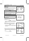
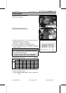
Disconnect the alternator lead connector [A].
○
Connect the hand tester as shown in the table 1.
○
Start the engine.
○
Run it at the rpm given in the table 1.
○
Note the voltage readings (total 3 measurements).
Table 1 Alternator Output Voltage
Connections
Tester
Range
Tester (+) to Tester (–) to
Reading
@4 000 rpm
250 V AC One B lack lead
Another Black lead 60 V or m ore
If the output voltage shows the value in the table, the al-
ternator operates properly.
If the output voltage shows a much higher than the value
in the table, the regulator/rectifier is damaged. A much
lower reading than that given in the table indicates that
the alternator is defective.
•
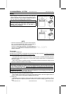
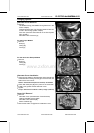
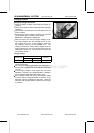
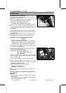
Check the stator coil resistance as follows.
○
Stop the engine.
○
Connect the commercially available tester as shown in the
table 2.
○
Note the readings (total 3 measurement).
Table 2 Stator Coil Resistance
Connections
Tes te r
Range
Tester (+) to Tester (–) to
Reading
×1Ω One Bla ck lead
Another Black lead
0.1 ∼ 0.2 Ω
If there is more resistance than shown in the table, or
no tester reading (infinity) for any two leads, the stator
has an open lead and must be replaced. Much less than
this resistance means the stator is shorted, and must be
replaced.
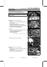
•
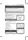
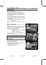
Using the highest resistance range of the hand tester,
measure the resistance between each of the black leads
and chassis ground.
Any hand tester reading less than infinity (∞) i ndicates a
short, necessitating stator replacement.
If the stator coils have normal resistance, but the voltage
check showed the alternator to be defective; then the rotor
magnets have probably weakened, and the rotor must be
replaced.
Special Tool - Hand Tester: 57001-1394
www.zxforums.com
www.zxforums.com
www.zxforums.com
www.zxforums.com
www.zxforums.com
www.zxforums.com
www.zxforums.com