


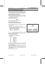
FUEL SYSTEM (DFI) 3-75
Gear Position Switch (Service Code 25)
Gear Position Switc h Removal/Installation
•
Refer to the Gear Position Switch Removal/Installation in
the Electrical System chapter (see Gear Position Switch
Removal/Installation in the Electrical System chapter).
Gear Position Switch Inspection
•
Refer to the Gear Position Switch Inspection in the Electri-
cal System chapter (see Gear Position Switch Inspection
in the Electrical System chapter).
Input Voltage Inspection
NOTE
○
Be sure the battery is fully charged.
•
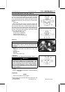
Turn the ignition switch OFF.
•
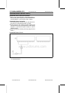
Remove the ECU (see ECU Removal).
○
Do not disconnect the ECU connectors.
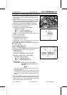
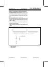
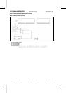
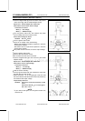
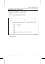
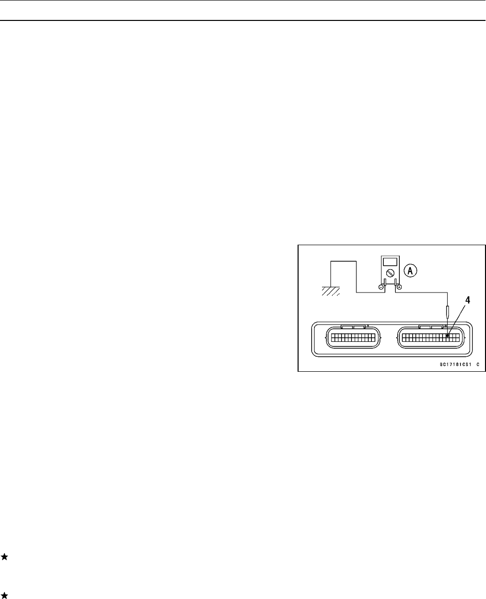
•
Connect a digital meter [A] to the connector, with the nee-
dle adapter set.
Special Tool - Needle Adapter Set: 57001-1457
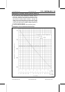
Gear Position Switch Input Voltage at 1 ∼ 6 Gear Positions
Connections to ECU Connector
Meter (+) → W/Y lead (terminal 4)
Meter (–) → Engine Ground
•
Measure the switch input voltage with the engine stopped,
and with the connector joined.
•
Turn the ignition switch ON.
Input Voltage at 1 ∼ 6 Gear Positions
Standard:
1st About 3.0 V
2nd About 2.5 V
3rd About 2.0 V
4th About 1.5 V
5th About 1.1 V
6th About 0.7 V
If the reading is out of the range, check the gear position
switch (see Gear Position Switch Inspection in the Elec-
trical System chapter).
If the switch is good, check the ECU for its ground and
power supply (see ECU Power Supply Inspection). If the
ground and power supply are good, replace the ECU (see
ECU section).
•
Turn the ignition switch OFF.
www.zxforums.com
www.zxforums.com
www.zxforums.com
www.zxforums.com
www.zxforums.com
www.zxforums.com
www.zxforums.com