


16-102 ELECTRICAL SYSTEM
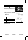
Switches and Sensors
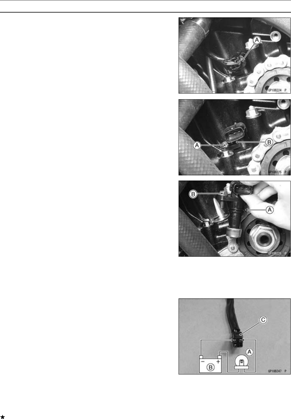
•
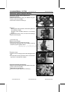
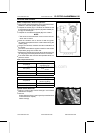
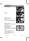
Disconnect the connector [A].
•
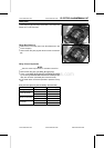
Remove:
Bolt [A]
Speed Senor [B]
Speed Sensor Installa tion
•
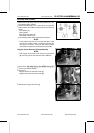
Apply grease to the new O-ring [A].
•
Set the speed sensor bolt [B].
•
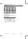
Tighten:
Torq ue - Speed Se nsor Bolt : 10 N·m (1.0 kgf· m, 89 in·lb)
•
Install the removed parts (see appropriate chapters).
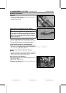
Speed Sensor Inspection
•
Refer to the Speed Sensor section i n the Fuel System
(DFI) chapter (see Speed Sensor section in the Fuel Sys-
tem (DFI) chapter).
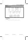
Fuel Reserve Switch Inspection
•
Fill the fuel tank with fuel.
•
Close the fuel tank cap s urely.
•
Remove the fuel tank (see Fuel Tank Removal in the Fuel
System (DFI) c hapter).
•
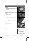
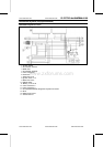
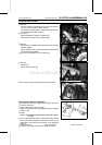
Connect the test light [A] (12 V 3.4 W bulb in a socket with
leads) and the 12 V battery [B] to the fuel pump connector
[C].
Connections
Battery (+) → 12 V 3.4 W Bulb (one side)
12 V 3.4 W Bulb (other side) → BK/R Lead Terminal
Battery (–) → BK/W Lead Terminal
Special Tool - Needle Adapter Set: 57001-1457
If the test light turn on, the reverse switch is defective.
Replace the fuel pump.
www.zxforums.com
www.zxforums.com
www.zxforums.com
www.zxforums.com
www.zxforums.com
www.zxforums.com
www.zxforums.com