


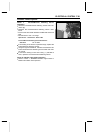
ELECTRICAL SYSTEM 17-77
Actuator Control System
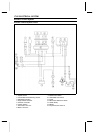
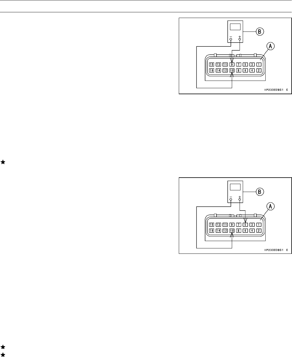
Check 3. Controller Power Supply Inspection
NOTE
○
Be sure the battery is fully charged.
•
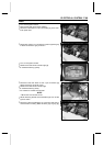
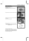
Remove:
Seat (see Frame chapter)
•
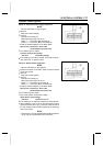
Connect:
Controller Connector [A]
Hand Tester [B] (range: DC 25 V)
Tester (+ ) → Connector (BR) Terminal [9]
Tester ( –) → Connector (BK/Y) Terminal [10]
○
Install the needle adapters on the tester leads.
Special Tools - Hand Tester: 57001-1394
Needle Adapter Set: 57001-1457
•
Turn ON the ignition switch.
Controller Power Supply Voltage
Standard:
near Battery Voltage
If the reading is not battery voltage, check the wiring har-
ness, 30 A fuse, or ignition switch.
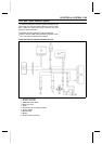
Check 4. Speed Sensor Inspection
NOTE
○
Be sure the battery is fully charged.
•
Support the vehicle on a stand or a jack so that the wheels
are off the ground.
•
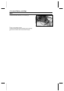
Remove:
Seat (see Frame chapter)
•
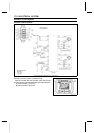
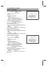
Connect:
Controller Connector [A]
Hand Tester [B] (range: DC 25 V)
Tester (+ ) → Connector (P) Terminal [5]
Tester ( –) → Connector (BK/Y) Terminal [10]
○
Install the needle adapters on the tester leads.
Special Tools - Hand Tester: 57001-1394
Needle Adapter Set: 57001-1457
•
Turn ON the ignition switch.
•
Spin a rear wheel, measure the voltage.
Speed Sensor Output Voltage
Standard: repeat from 0 to 5 V
If the reading is not standard, replace the speed sensor.
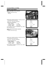
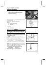
When installing a new O-ring on the speed sensor, apply
grease all around the O-ring. Insert the speed sensor to
the fully seated position before tightening the mounting
bolt for the sensor.
NOTE
○
If the sensor is not fully seated before tightening the bolt,
the O-ring can be damaged and oil may leak.