CONVERTER SYSTEM 6-25
Driven Pulley
•
Hold the drive & driven pulley holder in a vise.
Special Tool - Drive & Driven Pulley Holder: 57001-1473
•
Screw the guide bar into the holder.
Special Tool - Spring Holder Set: 57001-1483
•
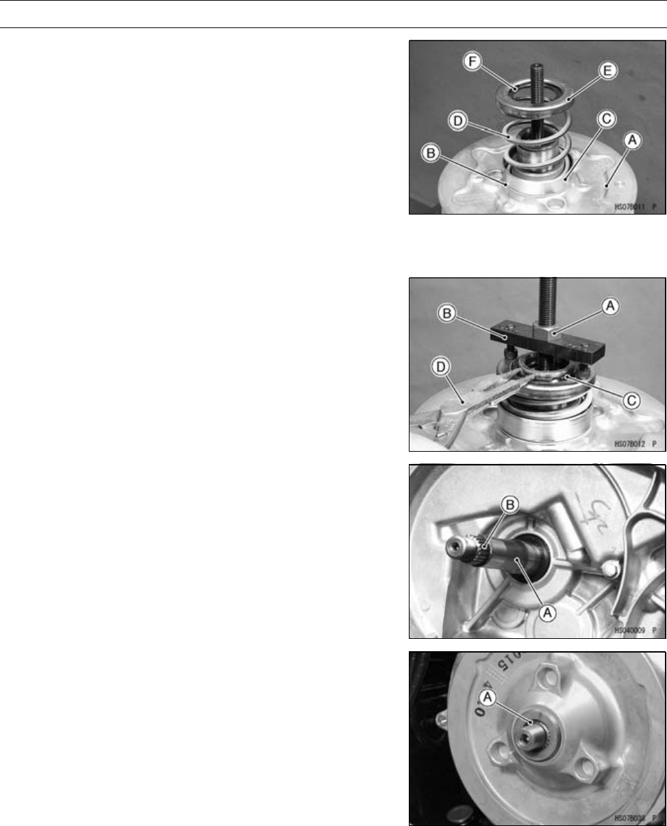
Put the driven pulley [A] onto the guide bar.
•
Put the thrust plate [B] so that the alloy side (gray) faces
the m ovable sheave.
•
Install:
Spring Seat [C]: 18.5 mm (0.728 in.)
Spring [D]
Spring Seat [E]: 9.3 mm (0.366 in.)
Circlip [F]
•
Tighten nut [A], and compress the spring with the spring
holder [B].
Special Tool - Spring Holder Set: 57001-1483
•
Install a new circlip [C] with circlip pliers [D].
Special Tool - Circlip Pliers: 57001-154
•
Remove the driven pulley from the spring holder set.
•
Clean the surface of the sheaves with an oil-less cleaning
fluid.
Driven Pulley Installatio n
•
Clean the transmission driven shaft [A].
•
Install:
Driven Pulley
NOTE
○
When engaging the spline on the driven pulley with
the spline [B] on the shaft, do not damage the pulley’s
spline. If any damage occurs, remove it with a file.
•
Clean the threads of the driven shaft and driven pulley
ends to open the air vent passage. Wipe off any extra
grease.
○
Wipe off any protruding grease [A].


