


ENGINE TOP END 5-33
Valves
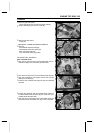
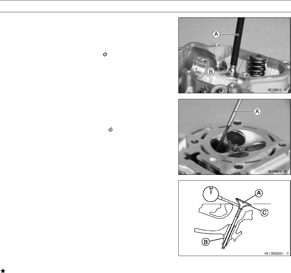
Valve Guide Installation
•
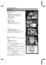
Lightly oil the valve guide outer surface.
•
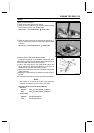
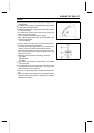
Using the valve guide arbor [A], drive the valve guide [B]
until its flange touches the cylinder head.
Special Tool - Valve Guide Arbor, 5: 57001-1203
•
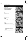
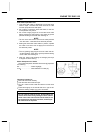
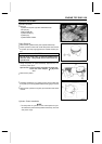
Ream the valve guide with the valve guide reamer [A] , if
may be necessary to ream the guide even if the old guide
is reused.
Special Tool - Valve Guide Reamer, 5: 57001-1204
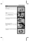
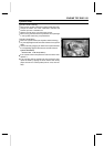
Valve-to-Guide Clearance Measurement
If a small bore gauge is not available, inspect t he valve
guide wear by measuring the valve to valve guide clearance
with the wobble method as indicated below.
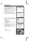
•
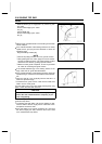
Insert a new valve [A] into the guide [B] and set a dial
gauge against the stem perpendicular to it as close as
possible to the cylinder head mating surface.
•
Move [C] t he stem back and forth to measure valve/valve
guide clearance.
•
Repeat the measurement in a direction at a right angle to
the first.
If the reading exceeds the service limit, replace the guide.
NOTE
○
The reading is not actual valve/valve guide clearance
because the measuring point is above the guide.
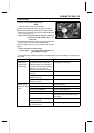
Valve/Valve G uide Clearance (Wobble Method)
Standard:
Exhaust 0.09 ∼ 0.17 mm (0.0035 ∼ 0.0067 in.)
Inlet 0.03 ∼ 0.11 mm (0.0012 ∼ 0.0043 in.)
Service Limit:
Exhaust 0.37 mm (0.0146 in.)
Inlet 0.31 mm (0.0122 in.)