


CONVERTER SYSTEM 6-17
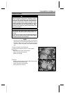
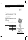
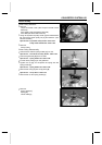
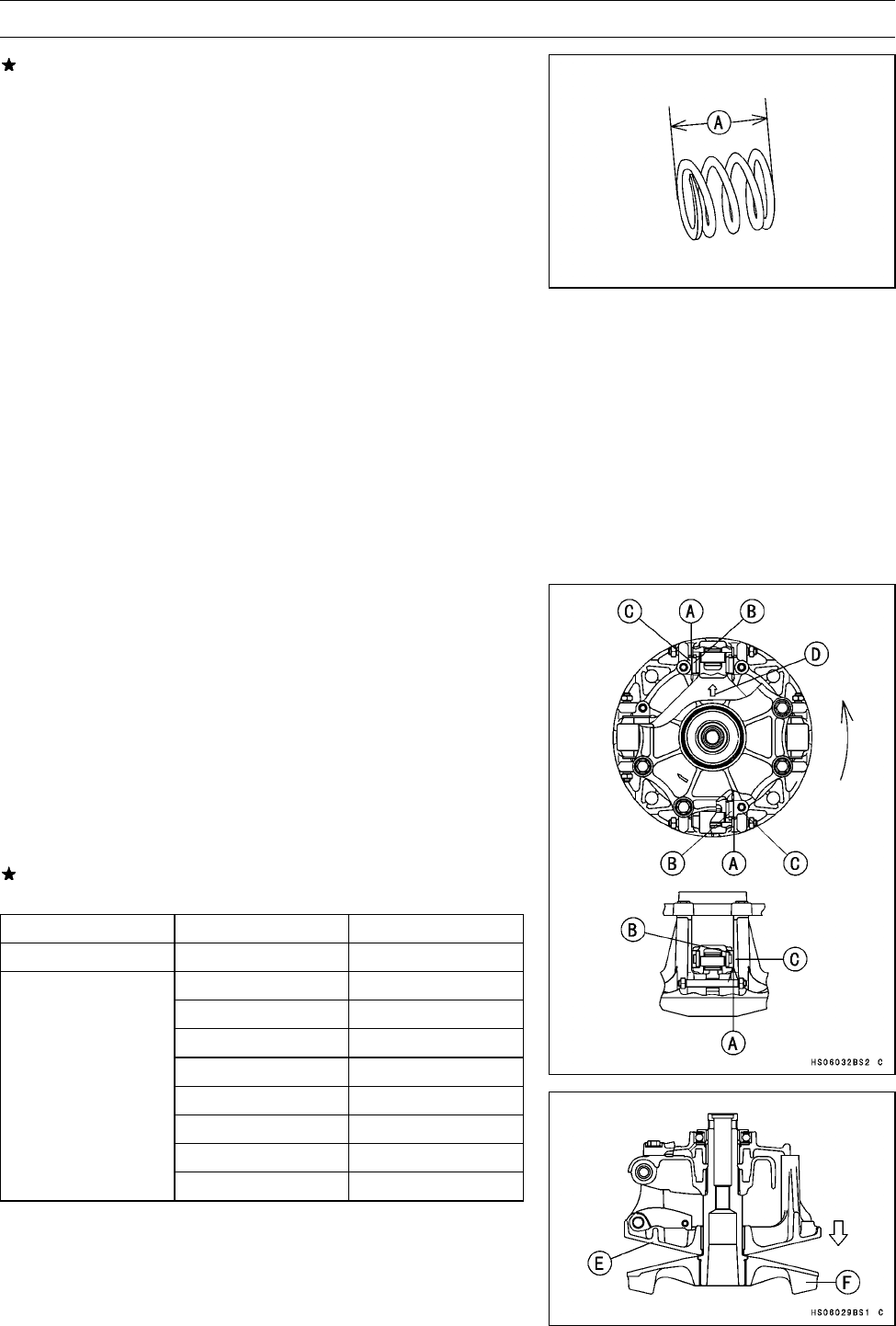
Drive Pulley
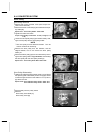
If the spring is worn or damaged, replace the spring.
Spring Free Length [A]
Standard: 60.4 mm (2.38 in.)
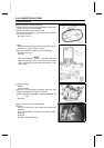
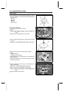
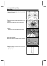
Spider Shoe Side Clearance Adjustment
•
Remove:
Drive Pulley (see Drive Pulley Removal)
Drive Pulley Cover and Spring (see Drive Pulley Disas-
sembly)
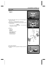
•
Temporarily install the following parts on the movable
sheave.
Dowel Pins (2)
Drive Pulley Cover
Two Bolts (at dowel pins)
○
Do not install the spring.
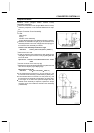
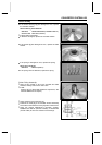
•
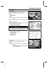
Turn the movable sheave counterclockwise.
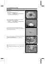
•
Measure the resulting clearance [A] between the shoe [B]
and the post [C] on the movable sheave at two positions
as shown.
[D] Arrow Mark
Shoe Side Clearance
Standard: up to 0.20 mm (0.008 in.), and there must
be kept a clearance which the movable
sheave [E] moves smoothly until it
touches the fixed sheave [F] with its own
weight.
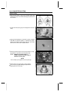
If the clearance is not the specified range, adjust it using
the following shoes.
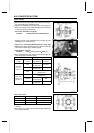
Part Number Thickness
Standard Shoe
49048-1090
7.5 mm (0.295 in.)
49048-1087
7.2 mm (0.283 in.)
49048-1088
7.3 mm (0.287 in.)
49048-1089
7.4 mm (0.291 in.)
49048-1091
7.6 mm (0.299 in.)
49048-1092
7.7 mm (0.303 in.)
49048-1093
7.8 mm (0.307 in.)
49048-1094
7.9 mm (0.311 in.)
Adjustment Shoes
49048-1095
8.0 mm (0.315 in.)