


ELECTRICAL SYSTEM 17-65
Meter
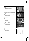
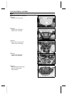
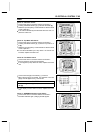
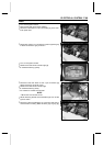
Check 4: Odom eter Check
•
Connect the wires in the same manner as Check 3.
•
Pushing the MODE button [A], cycles the odometer [B].
•
Raise the input frequency of t he oscillator to see the result
of this inspection.
If the value indicated by the odometer does not work, r e-
place the meter unit.
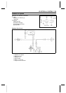
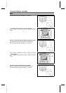
Check 5: Trip Meter A/B Check
•
Connect the wires in the same manner as Check 3.
•
Pushing the MODE button [A], cycles the trip m eter A or
B[B].
•
Raise the input frequency of t he oscillator to see the result
of this inspection.
If the value indicated by the trip meter A or B does not
increase, replace the meter unit.
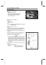
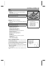
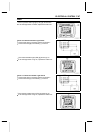
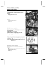
Check 6: Fuel Meter Check
•
Connect the wires in the same manner as Check 1.
○
The first segment (LCD) [A] should flash.
It the segment (LCD) does not flash, replace the meter
unit.
•
Connect terminal [5] to the battery (–) terminal.
○
When terminal [5] is connected, one segment in the fuel
gauge should appear every 15 seconds.
CAUTION
When all segments appeared, disconnect the t ermi-
nal [5].
If this display function does not work, replace the meter
unit.
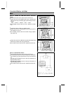
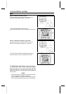
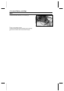
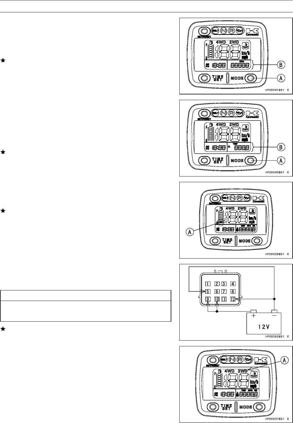
Check 7: 2WD/4WD Indicator Lights Check
•
Connect the wires in the same manner as Check 1.
○
The 2WD indicator light (LCD) [A] should appear.