


ELECTRICAL SYSTEM 17-79
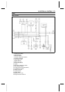
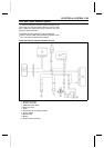
Actuator Control System
•
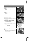
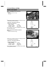
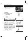
Disconnect the speed sensor lead connector.
•
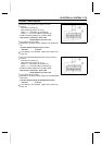
Connect:
Controller Connector [A]
Hand Tester [B] (range: DC 10 V)
Tester (+ ) → Connector (P) Terminal [5]
Tester ( –) → Connector (BK/Y) Terminal [10]
○
Install the needle adapters on the tester leads.
Special Tools - Hand Tester: 57001-1394
Needle Adapter Set: 57001-1457
•
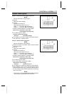
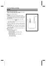
Turn ON the ignition switch.
•
Measure the controller output voltage for the speed sen-
sor.
Controller Output Voltage (to speed sensor)
Standard: 5 ±0.25 V
If the reading is not standard, replace the actuator con-
troller unit.
•
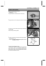
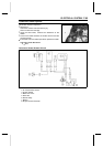
Disconnect the 2WD/4WD shift switch lead connector.
•
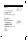
Connect:
Controller Connector [A]
Hand Tester [B] (range: DC 10 V)
Tester (+ ) → Connector (G) Terminal [7]
Tester ( –) → Connector (BK/Y) Terminal [10]
○
Install the needle adapters on the tester leads.
Special Tools - Hand Tester: 57001-1394
Needle Adapter Set: 57001-1457
•
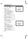
Turn ON the ignition switch.
•
Measure the controller output voltage for t he 2W D/4WD
shift switch.
Controller O utput Voltage (to 2WD/4WD shift switch)
Standard: 5 ±0.25 V
If the reading is not standard, replace the actuator con-
troller unit.