


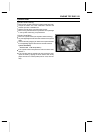
5-30 ENGINE TOP END
Cylinder Head
Cylinder Head Removal
•
Drain the coolant (see Coolant Change in Periodic Main-
tenance chapter).
•
Remove:
Carburetor (see Fuel System chapter)
Exhaust Pipe (see Engine Top End chapter)
Thermostat (see Cooling System chapter)
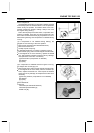
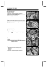
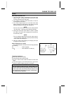
Spark Plug Cap [A]
Water Pipe Bolt [B]
Left Water Pipe [C]
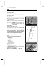
•
Remove:
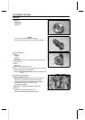
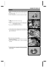
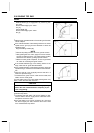
Water Pipe Bolts [A]
Right Water Pipe [B]
Vacuum Hoses [C]
Rocker Case (see Rocker Case Removal)
Camshaft (see Camshaft Removal)
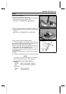
•
Remove:
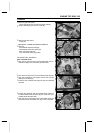
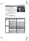
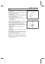
Cylinder Head Bolt (M6) [A]
Cylinder Head Bolts (M10) [B] and Washers
Cylinder Head [C] and Gasket
○
Lift the cylinder head to clear the dowel pins in the cylin-
der, and slide the cylinder head out of the frame.
Cylinder Head Installation
•
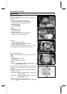
Apply oil to the O-rings on the oil pipe [A], and insert the
pipe.
•
Install:
Camshaft Chain G uides [B]
Dowel Pins [C]
New Cylinder Head Gasket [ D]
•
Tighten:
Torque - Front Cylinder Camshaft Chain Guide Bolt: 20
N·m (2.0 kgf·m, 14 ft·lb)
•
Apply molybdenum disulfide oil to the threads and seating
surface of the cylinder head bolts and both sides of the
washers.
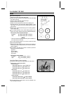
•
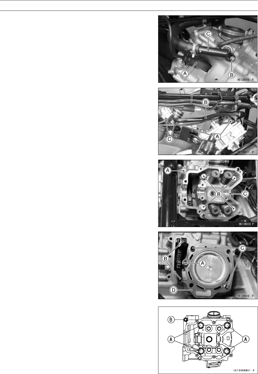
Tighten the cylinder head bolts [A] following the tightening
sequence as shown.
First Torque - Cylinder Head Bolts (M10): 25 N·m (2.5
kgf·m, 18 ft·lb)
Final Torque - Cylinder Head Bolts (M10): 49 N·m (5.0
kgf·m, 36 ft·lb)
•
Tighten the cylinder head bolts (M6) [B].
Torque - Cylinder Head Bolts (M6): 9.8 N·m (1.0 kgf·m, 87
in·lb)