


CRANKSHAFT/TRANSMISSION 10-15
Crankshaft/Connection Rod
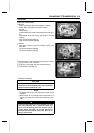
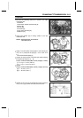
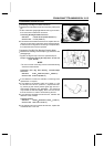
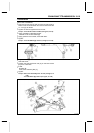
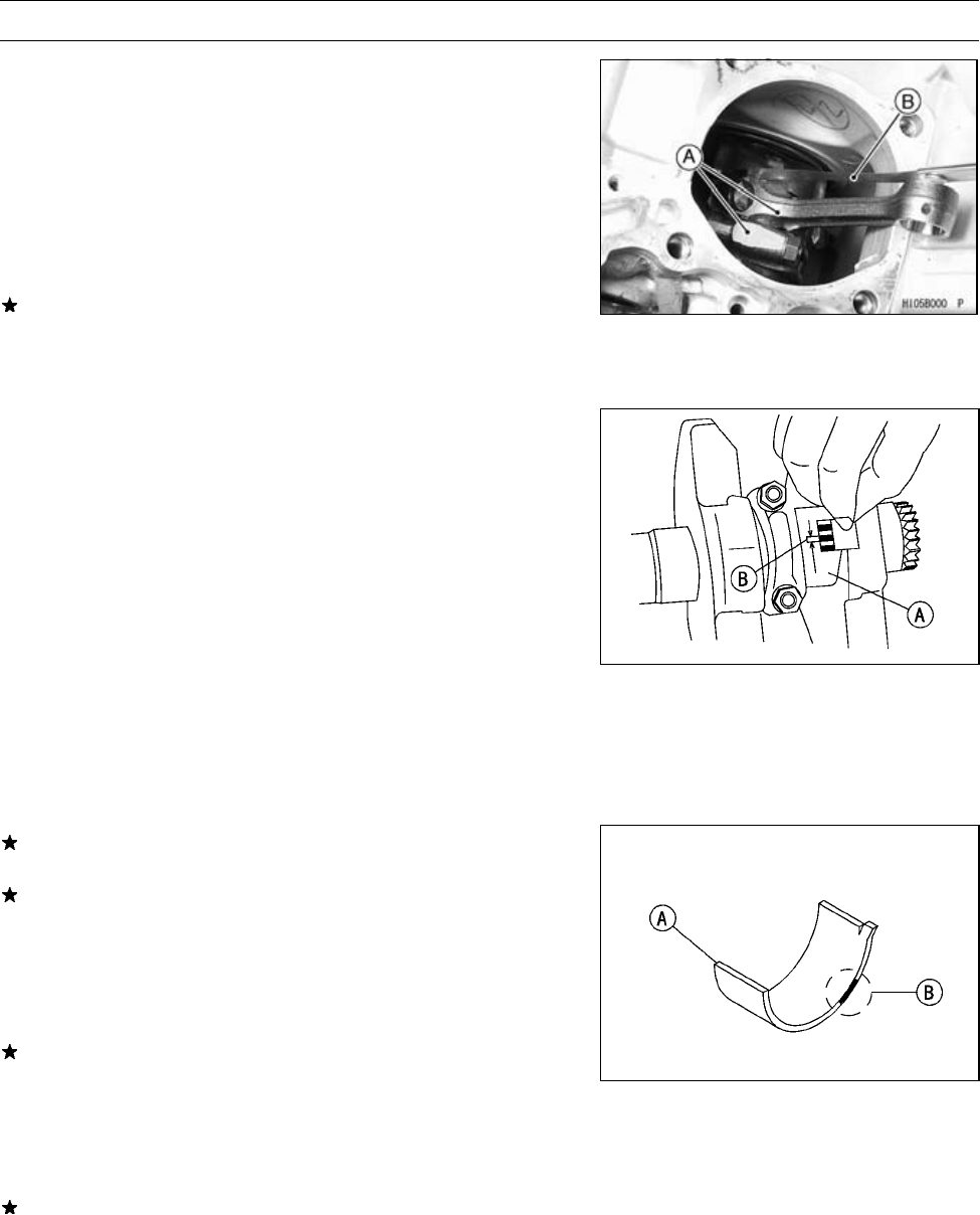
Connecting R od Big End Side Clearance
•
Measure the side clearance of the connecting rod big end
[A].
○
Insert a thickness gauge [B] between the big end and ei-
ther crank web to determine clearance.
Connecting Rod Big End Side Clearance
Standard: 0.16 ∼ 0.46 mm (0.0063 ∼ 0.0181 in.)
Service Limit: 0.7 mm (0.028 in.)
If the clearance exceeds the service limit, replace the con-
necting rod with new one and then check clearance again.
If clearance is too large after connecting rod replacement,
the crankshaft also must be replaced.
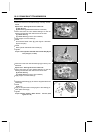
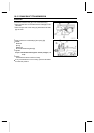
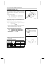
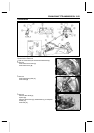
Connecting Rod Big End Bearing/Crankpin Wear
•
Measure the bearing insert/crankpin [A] clearance with
plastigage [B].
○
Tighten the big end cap nuts to the specified torque.
Torque - Connecting Rod Big End Cap Nuts: 34 N·m (3.5
kgf·m, 25 f t·lb)
NOTE
○
Do not move the connecting rod and crankshaft during
clearance measurement.
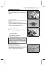
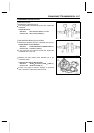
Connecting Rod Big End Bearing, Insert/Crankpin
Clearance
Standard: 0.028 ∼ 0.052 mm (0.0011 ∼ 0.0020 in.)
Service Limit: 0.09 mm (0.0035 in.)
If the clearance is within the standard, no bearing insert
replacement is required.
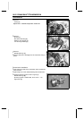
If the clearance is between 0.052 mm (0.0020 in.) and
the service limit 0.09 m m (0.0035 in.), replace the bear-
ing inserts [A] with inserts painted green [B]. Check in-
sert/crankpin clearance with plastigage. The clearance
may exceed the standard slightly, but it must not be less
than the minimum in order to avoid bearing seizure.
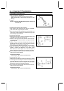
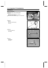
If the clearance exceeds the service limit, measure the
diameter of the crankpin.
Crankpin Diameter
Standard: 39.984 ∼ 40.000 mm (1.5742 ∼ 1.5748 in.)
Service Limit: 39.97 mm (1.5736 in.)
If the crankpin has worn past the service limit, replace the
crankshaft with a new one.