


6-20 CONVERTER SYSTEM
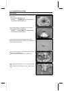
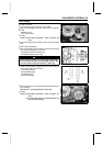
Drive Pulley
•
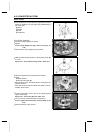
Remove the drive pulley holder and install three drive pul-
ley cover bolts to the specified torque.
•
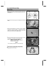
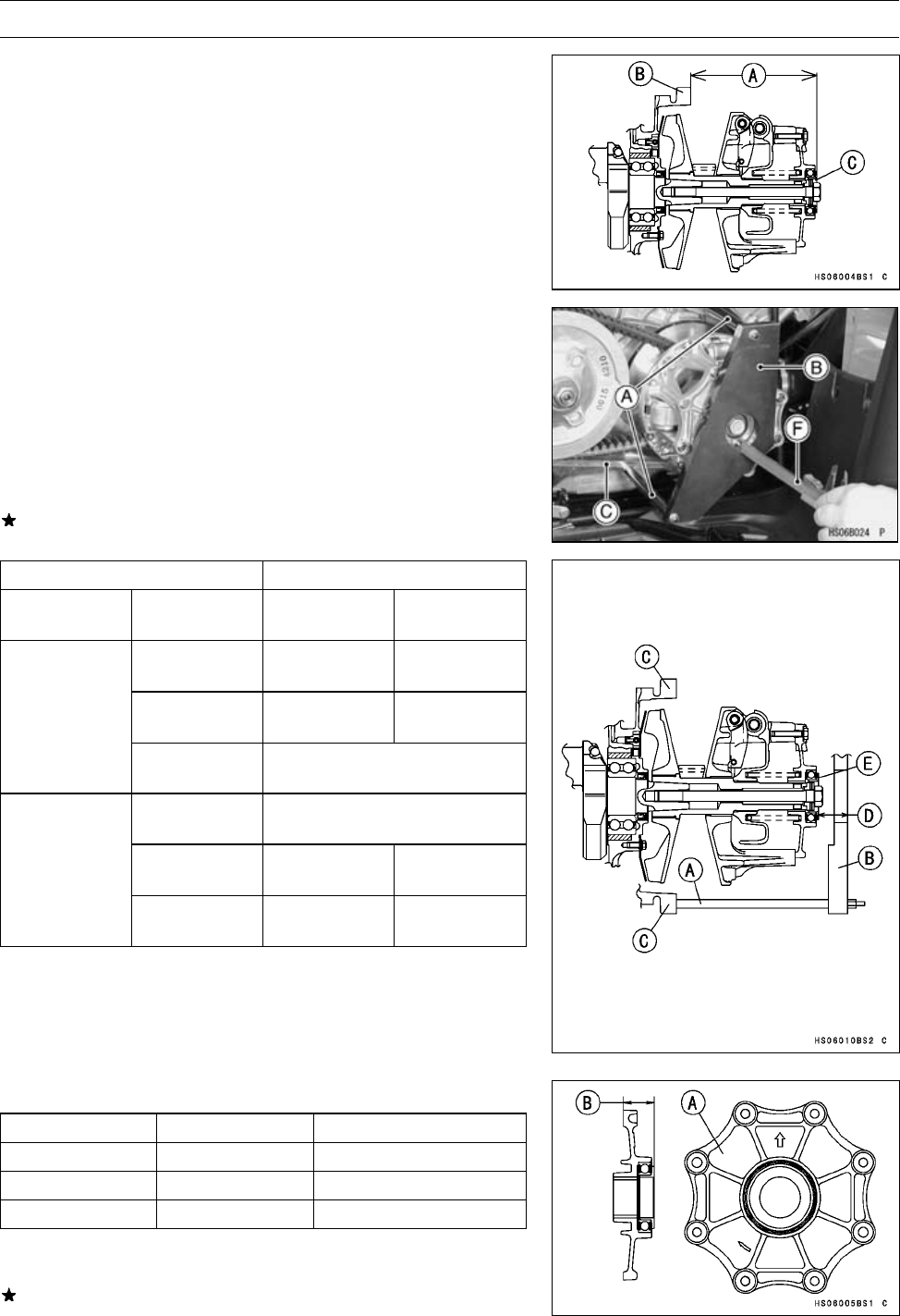
Adjust the installation length [A] of the drive pulley be-
tween the surface of the crankcase [B] and the collar [C]
on the drive pulley as followings.
Drive Pulley Installation Length [ A]
Standard: 149.85 ∼ 150.95 mm (5.900 ∼ 5.943 in.)
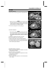
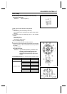
○
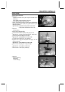
Install the drive pulley measurement tool (legs [A] and
plate [B]) on the crankcase [C].
Special Tool - Drive Pulley Measurement Tool: 57001-1498
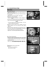
○
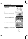
Measure the length [D] between the plate and collar [E]
with vernier calipers [F] or a depth gauge.
Measurement Length [D]
Standard: 14.55 ∼ 15.65 mm (0.573 ∼ 0.616 in.)
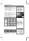
If the measurement is not within the specified range, ad-
just it according to following table.
Status Quo
Replacement Part
Measurement
Length
Paint Color
of Cover
Replace Part
(Part Number)
Paint Color
of Cover
Blue
Pulley Cover
(14041-1161)
No Paint
No Paint
Pulley Cover
(14041-1159)
Red
less than
14.55 mm
(0.573 in.)
Red
Drive Pulley Assembly
(49093-0014)
Blue
Drive Pulley Assembly
(49093-0014)
No Paint
Pulley Cover
(14041-1160)
Blue
more than
15.65 mm
(0.616 in.)
Red
Pulley Cover
(14041-1161)
No Paint
Drive Pulley Covers
Part Number
Paint Color [A]
Length [B]
14041-1159 Red
24.0 mm (0.945 in.)
14041-1160 Blue
25.4 mm (1.000 in.)
14041-1161 No Paint
24.7 mm (0.972 in.)
•
Measure the length again, after t he drive pulley cover is
replaces.
If the length is not within the specified length, replace the
drive pulley assembly.