


CRANKSHAFT/TRANSMISSION 10-13
Crankshaft/Connection Rod
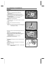
Crankshaft Removal
•
Split the crankcase (see Crankcase Disassembly).
•
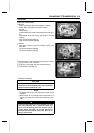
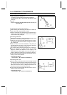
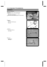
Remove the crankshaft [A] from the crankcase using a
press.
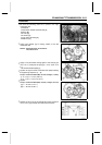
Crankshaft Installation
•
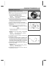
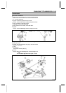
The left shaft [A] of the crankshaft is longer than the right
shaft [B].
•
Apply engine oil to the both main journals.
•
Insert the right crankshaft tapered end (the shorter end)
into the right crankcase using a press and two crankshaft
jigs.
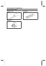
Special Tools - Crankshaft Jig: 57001-1174 × 2
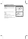
Connecting R od Removal
•
Remove the crankshaft (see Crankshaft Removal).
•
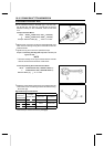
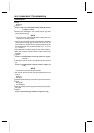
Remove the connecting rods [A] from the crankshaft.
NOTE
○
Mark and record the locations of the connecting rods
and their big end caps [B] so that they can be installed
in their original positions.
○
Remove the connecting rod big end nuts, and take off the
rod and cap with the bearing inserts.
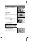
Connecting Rod Installation
CAUTION
If the connecting rods, bearing inserts, or crank-
shaft are replaced with new ones, select the bearing
insert and check clearance with a plastigage before
assembling the engine to be sure the correct bear-
ing inserts are installed.
•
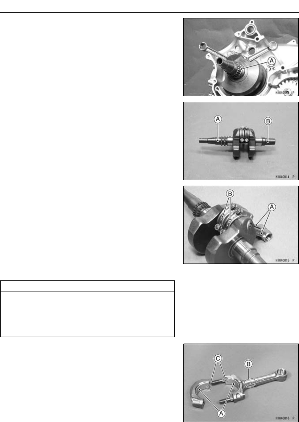
Apply molybdenum disulfide oil:
Inner Surface [A] of Bearing Inserts
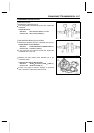
•
Face the “OUT” marks [B] of both c onnecting rods to-
wards the outsides of the crankshaft.
•
Fit the connecting rod cap so that the grooves [C] of the
cap and connecting rod are on the same side.