


6-18 CONVERTER SYSTEM
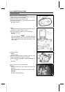
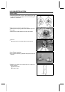
Drive Pulley
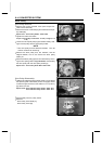
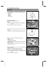
If the clearance is not the specified range after the above
shoes are replaced, use the spacer [A] (92026-0038) of
the option part.
[B] Shoe
[C] Spider
[D] Post
[E] Clearance
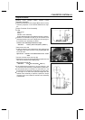
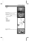
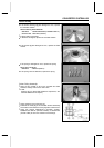
Drive Pulley Assembly
•
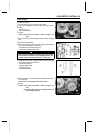
Install the ramp weight [A] as shown.
•
Tighten:
Torque - Ramp Weight Nuts [B]: 6.9 N·m (0.70 kgf·m, 61
in·lb)
•
Check that the ramp weights swing smoothly.
•
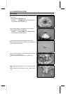
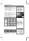
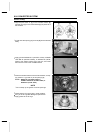
Hold the fixed sheave [A] with the drive pulley holder [B]
inavise.
Special Tool - Drive & Driven Pulley Holder: 57001-1473
•
Clean the threads of the fixed sheave and spider.
•
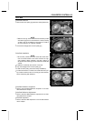
Install:
Movable Sheave
Spider [A] and Shoes [B]
○
Align t he arrow [C] on the spider with the arrow [D] on the
movable sheave.
○
Insert the shoes so that the rubber side (black, small di-
ameter) faces inward.
•
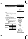
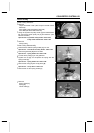
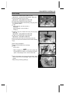
Put the drive pulley wrench [A] on the spider [B] and
tighten the bolt [C].
Special Tool - Drive Pulley Wrench: 57001-1474
•
Turn the wrench counterclockwise for tightening.
Torque - Spider (left-hand threads): 275 N·m (28 kgf·m, 203
ft·lb)
•
Remove the drive pulley wrench.