


6-22 CONVERTER SYSTEM
Driven Pulley
•
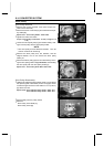
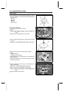
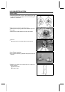
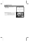
Confirm the paint mark “0” [A] on the movable sheave [B]
in alignment with the point [C] on the fixed sheave [D] for
phase fit of the sheaves.
•
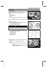
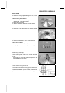
Wipe off the molybdenum disulfide grease.
•
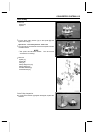
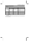
Remove the four pins [A] with a thin standard tip screw-
driver [B].
•
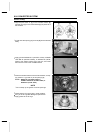
Remove the movable sheave from the fixed sheave.
•
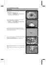
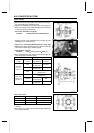
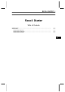
Remove:
Spacer(s) [A] (for Drive Belt Deflection Adjustment)
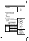
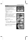
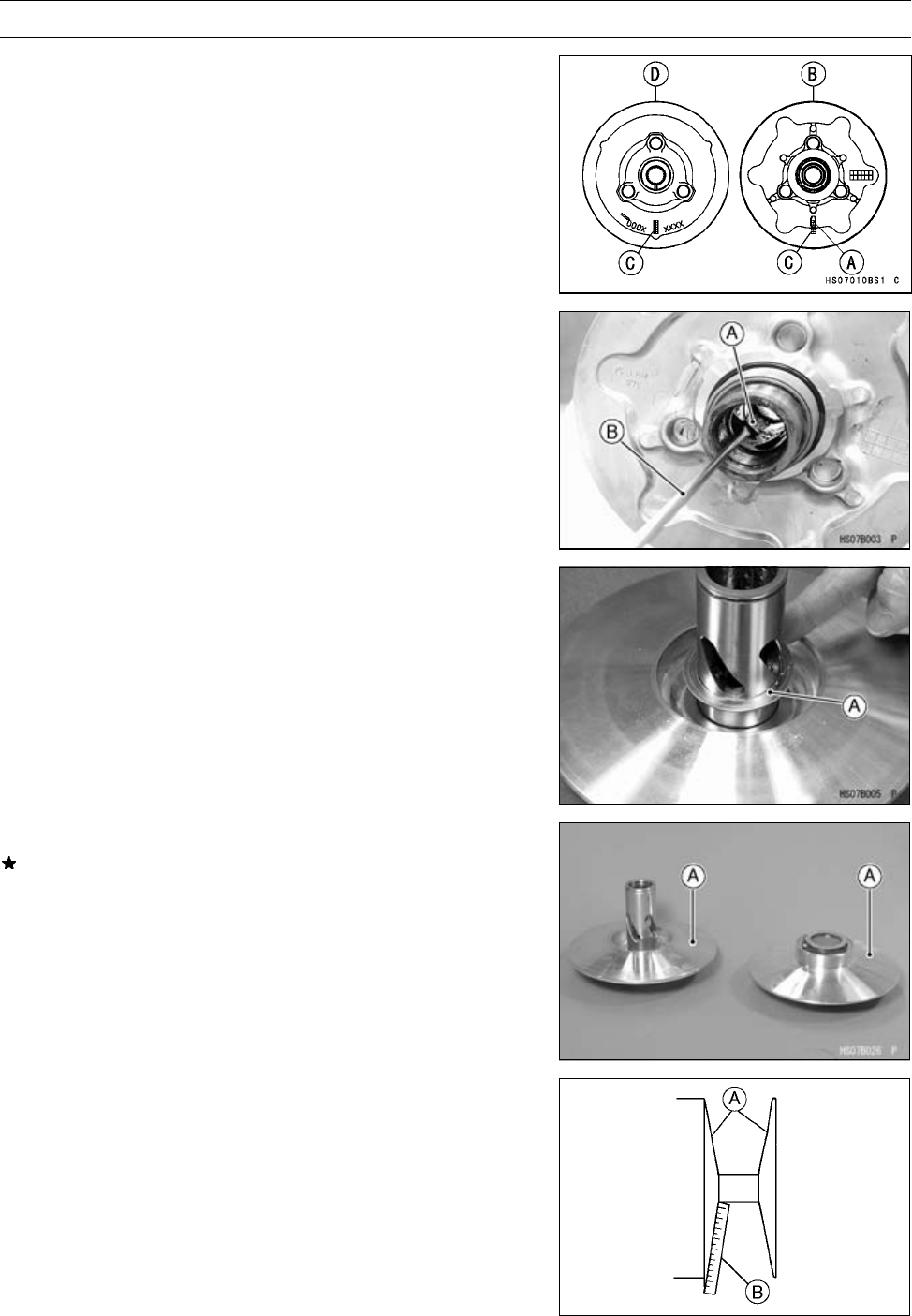
Driven Pulley Inspection
If the sheave surfaces [A] appear damaged, replace the
sheaves.
•
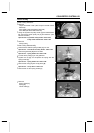
Replace the sheave w ith uneven wear on the belt con-
tacting surfaces.
[A] Sheave Surface
[B] Straight Edge