


5-16 ENGINE TOP END
Rocker Case
•
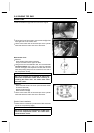
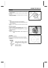
Insert a suitable bar [A] under the front of the engine.
•
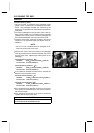
Lift [A] the front of the engine to remove the bolt [B] of the
front right side on the rocker case.
•
Lift the rocker case clear of the dowel pins in the cylinder
head and slide the rocker case out of the frame.
Rear Rocker Case
•
Remove:
Front Rocker Case (see this section)
Torque Converter Cover Upper Air Duct
•
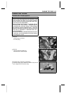
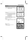
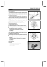
Using a wrench on the alternator bolt, turn the crankshaft
counterclockwise (270°) until “T-R” mark [A] is aligned
with the notch [B] in the inspection window, and the cam
lobes are pointing away from the rocker arms: the end of
the compression stroke.
CAUTION
Be sure to position the crankshaft at TDC of the
end of the com pression stroke when rem oving or
installing the rocker case. The rocker arms could
bend the valves.
•
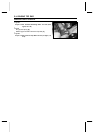
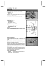
Remove:
Rear Camshaft Chain Tensioner (see Camshaft Chain
Tensioner Rem oval)
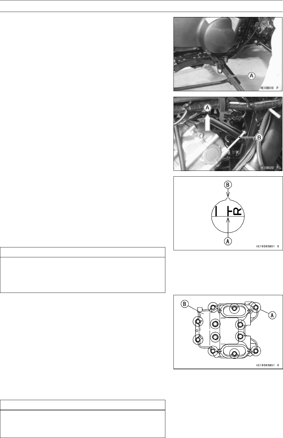
Rocker Case Bolts [A]
Rear Rocker Case [B]
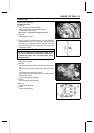
•
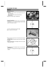
Lift the rocker case clear of the dowel pins in the cylinder
head and slide the rocker case out of the frame.
Rocker Case Installation
•
Check that the crankshaft is positioned at TDC and at the
end of the compression stroke.
CAUTION
Be sure to position the crankshaft is at TDC of the
end of the compression stroke. The rocker arms
could bend the valves.