


6-10 CONVERTER SYSTEM
Torque Converter
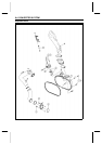
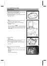
Torque C onverter Cover Installation
•
Check the actuator lever assembly installation length (see
Torque Converter Cover Assembly).
•
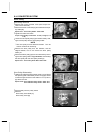
Fit the trim seal into the converter cover.
○
Set the trim seal juncture in the area [A] when insert the
trim seal in the cover.
[B] 10 mm (0.39 in.)
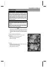
•
Check:
Drive Belt Failure Detection Switch (see Switch Inspec-
tion section in Electric System chapter)
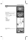
•
Set [A] the switch lever [B] to the ON mark side [C].
Converter Cover [D]
Front [E]
NOTE
○
The failure detection system is activated when the
switch is in the ON position. This is the normal running
mode. Engine rpm is limited when the switch i s in the
OFF position.
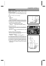
•
Tighten (loosely):
#3 Bolt
#1 and #2 Bolts
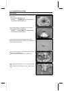
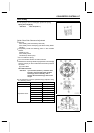
•
Press the cover downward and tighten the cover bolts
following the tightening sequence as shown.
Torque - Converter Cover Bolts: 8.8 N·m (0.90 kgf·m, 78
in·lb)
[A] Clamp
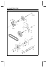
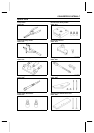
Torque Converter Cover Disassembly
•
Remove:
Torque Converter Cover (see Torque Converter Cover
Removal)
Engine Brake Actuator (see Electrical System chapter)
Circlip [A]
Spring [B]
Actuator Lever Assembly [C]