12-70 FIN AL DRIVE
Rear Final Gear Case
6. Pinion Gear Shims for Backlash Adjustment
Thickness Part Number
0.15 mm (0.006 in.)
92180-1423
0.2 mm (0.008 in.) 92180-1424
0.5 mm (0.020 in.) 92180-1425
0.8 mm (0.031 in.) 92180-1426
1.0 mm (0.039 in.) 92180-1427
1.2 mm (0.047 in.) 92180-1428
7. Ring Gear Shims for Tooth Contact Adjustment
Thickness Part Number
0.15 mm (0.006 in.) 92180-1417
0.2 mm (0.008 in.) 92180-1418
0.5 mm (0.020 in.)
92180-1419
0.8 mm (0.031 in.)
92180-1420
1.0 mm (0.039 in.)
92180-1421
1.2 mm (0.047 in.) 92180-1422
8. Ring Gear Shims for Tooth Contact Adjustment
Thickness Part Number
0.15 mm (0.006 in.) 92180-0166
0.2 mm (0.008 in.) 92180-0165
0.5 mm (0.020 in.) 92180-0164
0.8 mm (0.031 in.) 92180-0163
1.0 mm (0.039 in.) 92180-0162
1.2 mm (0.047 in.)
92180-0161
Backlash Adjustment
•
Clean any dirt and oil off the bevel gear teeth.
•
Install the pinion gear assembly with the primary shim 1.0
mm (0.039 in.) thickness.
•
Assemble the rear final gear case (see Rear Final Gear
Case Assembly).
○
Install the ring gear with the primary shims 1.0 mm (0.039
in.) thickness.
○
Check the backlash during t ightening the cover bolts, and
stop tightening them immediately if the backlash disap-
pears. Then, change the ring gear shim to a thinner one.
•
Temporarily, install the rear axle in the gear case and hold
it with a vise so that the ring gear is lower than the pinion
gear.
•
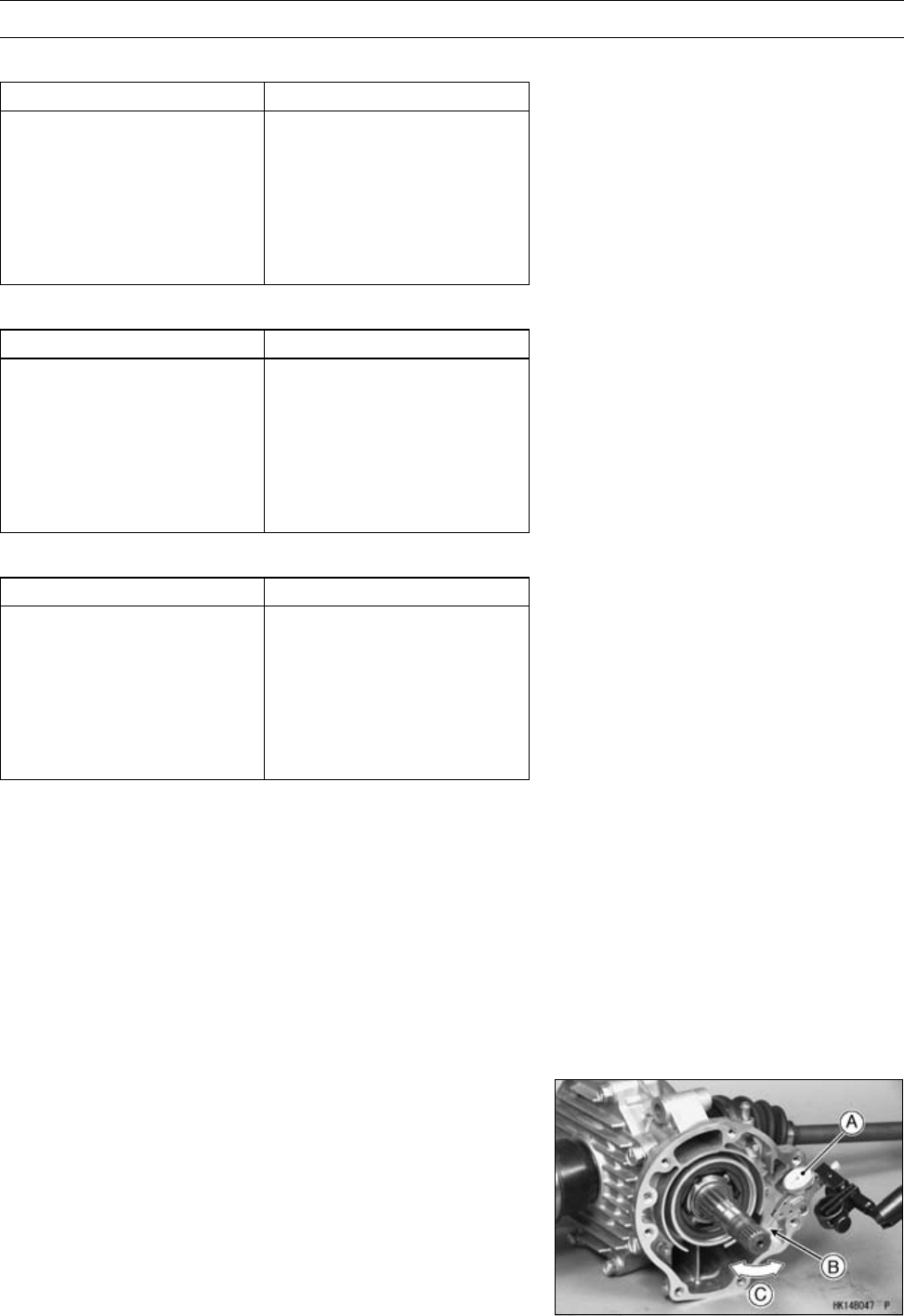
Mount a dial gauge [A] so that the tip of the gauge is
against the splined portion [B] of the pinion gear joint.
•
To measure the backlash, move the pinion gear shaft
back and forth [C] while holding the rear axle steady.
The difference between the highest and the lowest gauge
reading is the amount of backlash.
○
Measure backlash at three locations equally spaced on
the splines.
Rear Final Bevel Gear Backlash
Standard: 0.04 ∼ 0.17 mm (0.002 ∼ 0.007 in.) at
pinion gear spline


