


CONVERTER SYSTEM 6-11
Torque Converter
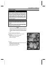
Actuator Lever (Engine Brake Control Lever)
Assembly Inspection
•
Refer to the Actuator Lever (Engine Brake Control Lever)
Assembly Inspection in the Periodic Maintenance chap-
ter.
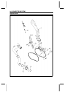
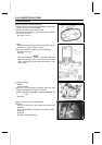
Torque Converter Cover Assem bly
•
Install:
New Circlip
Spring
Actuator Lever Assembly
Engine Brake Actuator (see Electrical System chapter)
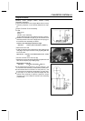
•
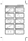
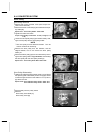
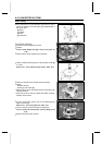
Measure the installation length [A] of the actuator lever
assembly between the cover end [B] and resin tips [C] on
the actuator lever assembly as follows:
Actuator Lever As sembly Installation Length
Standard: 149.33 ∼ 150.47 mm (5.879 ∼ 5.924 in.)
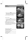
○
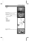
Remove the trim seal.
○
Install the actuator lever measurement tool (plate [A] and
rods [B]) on the torque converter cover [C] and tighten the
two cover bolts.
Special Tool - Actuator Lever Measurement Tool: 57001
-1499
○
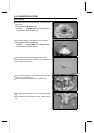
Set the rod ends on the resin tips [D].
○
Measure the recess length [E] between the plate and rods
with Vernier calipers [F] or depth gauge.
Measurement Length [E]
Standard: 1 .33 ∼ 2.47 mm (0.052 ∼ 0.097 in.)
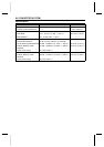
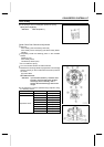
If the measurement is less than 1.33 mm (0.052 in.), use
the actuator lever assembly (13236-0046) of yellow paint.
If the m easurement is more than 2.47 mm (0.097 in.), use
the actuator lever assembly (13236-0047) of green paint.
If the l ength is not within the specified l ength after the
actuator lever assembly is replaced, replace the torque
converter cover, and install the actuator lever assembly
(13236-0048).