


10-2
SERVICING
INFORMATION
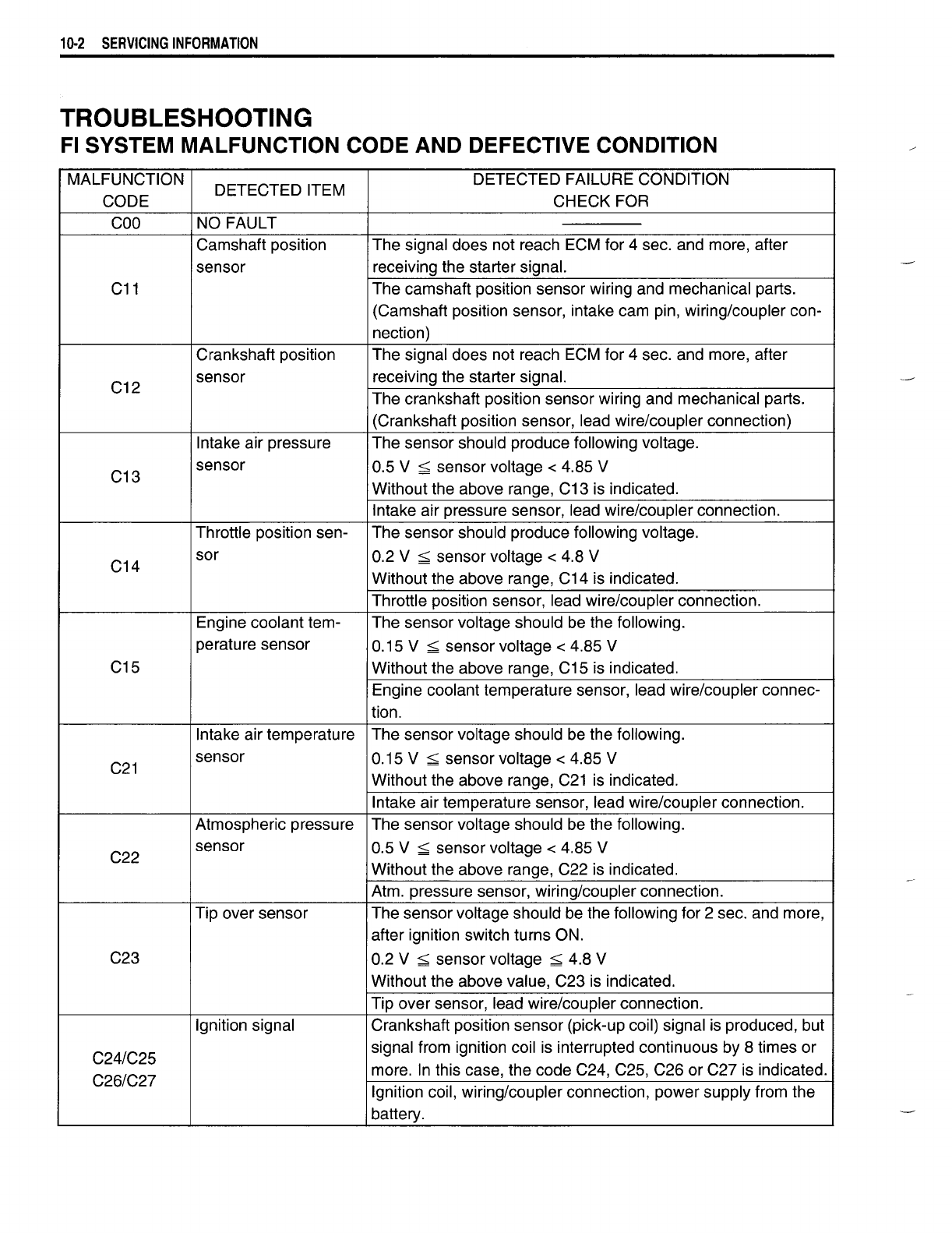
TROUBLESHOOTING
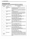
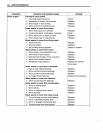
FI SYSTEM MALFUNCTION CODE AND DEFECTIVE CONDITION
MALFUNCTION
DETECTED ITEM
DETECTED FAILURE CONDITION
CODE CHECK FOR
COO
NO FAULT
Camshaft position The signal does not reach ECM for 4 sec. and more, after
sensor receiving the starter signal.
C11
The camshaft position sensor wiring and mechanical parts.
(Camshaft position sensor, intake cam pin, wiring/coupler con-
nection)
Crankshaft position The signal does not reach ECM for 4 sec. and more, after
C12
sensor receiving the starter signal.
The crankshaft position sensor wiring and mechanical parts.
(Crankshaft position sensor, lead wire/coupler connection)
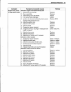
Intake air pressure The sensor should produce following voltage.
C13
sensor
0.5 V
;;;;;
sensor voltage < 4.85 V
Without the above range, C13 is indicated.
Intake air pressure sensor, lead wire/coupler connection.
Throttle position sen- The sensor should produce following voltage.
C14
sor
0.2 V
;;;;;
sensor voltage < 4.8 V
Without the above range, C14 is indicated.
Throttle position sensor, lead wire/coupler connection.
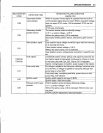
Engine coolant tem- The sensor voltage should be the following.
perature sensor
0.15 V
;;;;;
sensor voltage < 4.85 V
C15
Without the above range, C15 is indicated.
Engine coolant temperature sensor, lead wire/coupler connec-
tion.
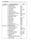
Intake air temperature The sensor voltage should be the following.
C21
sensor
0.15 V
;;;;;
sensor voltage < 4.85 V
Without the above range, C21 is indicated.
Intake air temperature sensor, lead wire/coupler connection.
Atmospheric pressure
The sensor voltage should be the following.
C22
sensor
0.5 V
;;;;;
sensor voltage < 4.85 V
Without the above range, C22 is indicated.
Atm. pressure sensor, wiring/coupler connection.
Tip over sensor The sensor voltage should be the following for 2 sec. and more,
after ignition switch turns ON.
C23
0.2 V
;;;;;
sensor voltage
;;;;;
4.8 V
Without the above value, C23 is indicated.
Tip over sensor, lead wire/coupler connection.
Ignition signal Crankshaft position sensor (pick-up coil) signal is produced, but
C24/C25
signal from ignition coil is interrupted continuous by 8 times or
C26/C27
more. In this case, the code C24, C25, C26 or C27 is indicated.
Ignition coil, wiring/coupler connection, power supply from the
battery.