


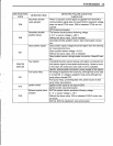
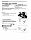
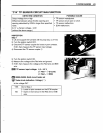
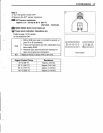

"C14" TP SENSOR CIRCUIT MALFUNCTION
FI
SYSTEM
DIAGNOSIS
4·33
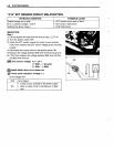
DETECTED CONDITION
POSSIBLE CAUSE
Output voltage low or high
• TP sensor maladjusted.
Difference between actual throttle opening and • TP sensor circuit open or short.
opening calculated by ECM in larger than specified • TP sensor malfunction.
value.
• ECM malfunction.
0.2 V
;;;;;
Sensor voltage < 4.8V
(without the above range.)
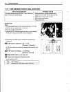
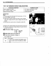
INSPECTION
Step 1
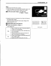
1) Lift and support the fuel tank with its prop stay. (c::::T5-5)
2) Turn the ignition switch OFF.
3) Check the TP sensor coupler for loose or poor contacts.
If OK, then measure the TP sensor input voltage.
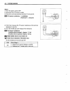
4) Disconnect the TP sensor coupler
CD.
5) Turn the ignition switch ON.
6) Measure the voltage at the Red wire and ground.
7) If OK, then measure the voltage at the Red wire and B/Br
wire.
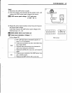
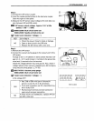
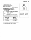
~
TP sensor
input
voltage: 4.5 - 5.5 V
(C±l
Red - 8 Ground)
(C±l
Red - 8 B/Br)
,Rfot.
09900-25008: Multi
circuit
tester set
~
Tester
knob
indication: Voltage
(=-=-=)
Is the voltage OK?
YES Go to Step 2.
• Loose or poor contacts on the ECM coupler.
NO • Open or short circuit in the Red wire or B/Br
wire.