


9·20
ELECTRICAL
SYSTEM
"-
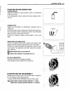
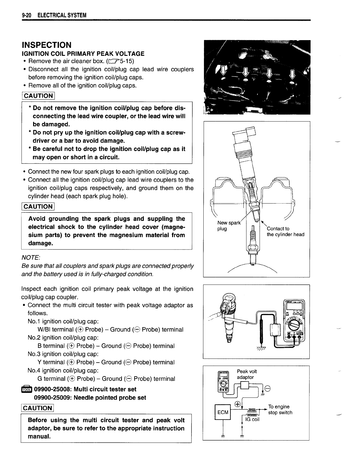
Contact to
the cylinder head
Avoid grounding the
spark
plugs and suppling the
electrical
shock
to the cylinder head cover (magne-
sium parts) to prevent the magnesium material from
damage.
INSPECTION
IGNITION COIL PRIMARY
PEAK
VOLTAGE
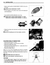
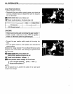
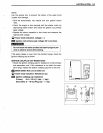
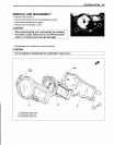
• Remove the air cleaner box.
(c::::75-15)
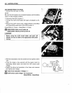
• Disconnect all the ignition coil/plug cap lead wire couplers
before removing the ignition coil/plug caps.
• Remove all of the ignition coil/plug caps.
I
CAUTION
I
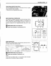
• Connect the new four spark plugs to each ignition coil/plug cap.
• Connect all the ignition coil/plug cap lead wire couplers to the
ignition coil/plug caps respectively, and ground them on the
cylinder head (each spark plug hole).
I
CAUTION
I
NOTE:
Be sure that
all
couplers
and
spark
plugs are connectedproperly
and
the battery used is in fully-charged condition.
* Do
not
remove the ignition coil/plug cap before dis-
connecting the lead wire coupler, or the lead wire will
be damaged.
* Do
not
pry up the ignition coil/plug cap with a screw-
driver or a bar to avoid damage.
* Be careful
not
to
drop
the ignition coil/plug cap as it
may open or
short
in a circuit.
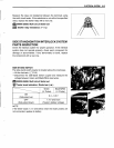
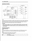
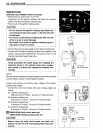
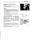
Inspect each ignition coil primary peak voltage at the ignition
coil/plug cap coupler.
• Connect the multi circuit tester with peak voltage adaptor as
follows.
NO.1
ignition coil/plug cap:
W/SI terminal
(CB
Probe) - Ground
(8
Probe) terminal
NO.2
ignition coil/plug cap:
S terminal
(CB
Probe) - Ground
(8
Probe) terminal
No.3 ignition coil/plug cap:
Y terminal
(CB
Probe) - Ground
(8
Probe) terminal
No.4 ignition coil/plug cap:
G terminal
(CB
Probe) - Ground
(8
Probe) terminal
i£ti
09900-25008: Multi
circuit
tester set
09900-25009: Needle pointed probe set
I
CAUTION
I
Before using the multi
circuit
tester and peak
volt
adaptor, be sure to refer to the appropriate instruction
manual.
I---L-~~_To
engine
stop switch