


FI
SYSTEM
DIAGNOSIS
4·17
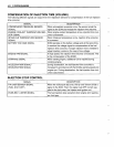
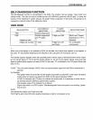
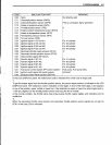
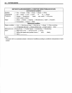
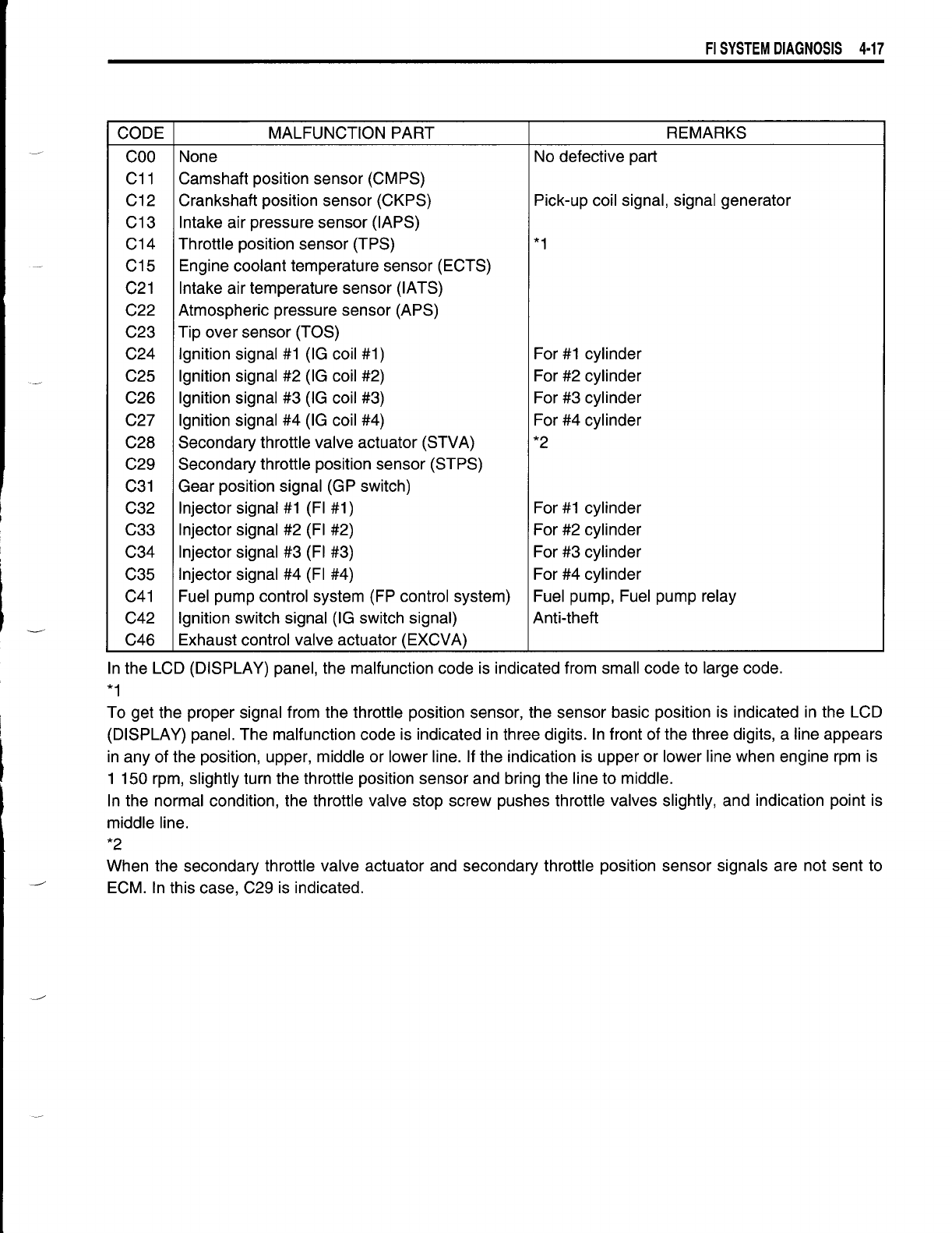
CODE MALFUNCTION PART REMARKS
COO
None
No defective part
C11
Camshaft position sensor (CMPS)
C12
Crankshaft position sensor (CKPS) Pick-up coil signal, signal generator
C13 Intake air pressure sensor (lAPS)
C14 Throttle position sensor (TPS)
*1
C15 Engine coolant temperature sensor (ECTS)
C21
Intake air temperature sensor (lATS)
C22 Atmospheric pressure sensor (APS)
C23 Tip over sensor (TOS)
C24 Ignition signal #1 (IG coil #1) For #1 cylinder
C25
Ignition signal #2 (IG coil #2) For #2 cylinder
C26
Ignition signal #3 (IG coil #3)
For #3 cylinder
C27
Ignition signal #4 (IG coil #4) For #4 cylinder
C28 Secondary throttle valve actuator (STVA)
*2
C29 Secondary throttle position sensor (STPS)
C31 Gear position signal (GP switch)
C32
Injector signal #1 (FI #1) For #1 cylinder
C33
Injector signal #2 (FI #2) For #2 cylinder
C34 Injector signal #3 (FI #3)
For #3 cylinder
C35
Injector signal #4 (FI #4)
For #4 cylinder
C41 Fuel pump control system (FP control system)
Fuel pump, Fuel pump relay
C42
Ignition switch signal (IG switch signal) Anti-theft
C46 Exhaust control valve actuator (EXCVA)
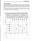
In the LCD (DISPLAY) panel, the malfunction code is indicated from small code to large code.
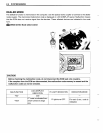
*1
To get the proper signal from the throttle position sensor, the sensor basic position is indicated in the LCD
(DISPLAY) panel. The malfunction code is indicated in three digits. In front of the three digits, a line appears
in any of the position, upper, middle or lower line. If the indication is upper or lower line when engine rpm is
1 150 rpm, slightly turn the throttle position sensor and bring the line to middle.
In the normal condition, the throttle valve stop screw pushes throttle valves slightly, and indication point is
middle line.
*2
When the secondary throttle valve actuator and secondary throttle position sensor signals are not sent to
ECM. In this case, C29 is indicated.