


4·40
FI
SYSTEM
DIAGNOSIS
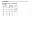
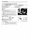
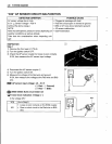
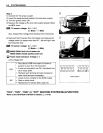
"C22" AP SENSOR CIRCUIT MALFUNCTION
DETECTED
CONDITION
POSSIBLE
CAUSE
AP
sensor
voltage
low
or high.
•
Clogged
air
passage
with dust.
0.5
V
;;;;;
Sensor
voltage
< 4.S5 V
•
Red wire circuit open or
shorted
to
ground
.
(without
the
above
range.)
•
B/Br
or
G/Y
wire circuit
shorted
to ground.
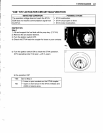
NOTE:
• AP
sensor
malfunction.
Note that atmospheric pressure varies depending on •
ECM
malfunction.
weather conditions as well as altitude.
Take that into consideration when inspecting volt-
age.
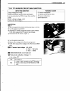
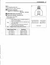
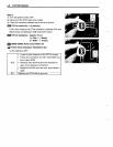
INSPECTION
Step
1
1)
Remove
the
front seat.
(CTS-6)
2)
Turn
the ignition
switch
OFF.
3)
Check
the AP
sensor
coupler
for
loose
or
poor
contacts.
If OK,
then
measure
the AP
sensor
input voltage.
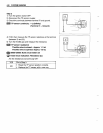
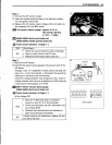
4)
Disconnect
the
AP
sensor
coupler
CD.
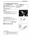
5)
Turn
the ignition switch
ON.
6)
Measure
the
voltage
at the Red wire and ground.
If
OK,
then
measure
the
voltage
at
the
Red
wire
and
B/Br
wire.
B
AP
sensor
input
voltage:
4.5
-
5.5
V
(CB
Red
- 8
Ground)
(CB
Red
- 8
B/Br)
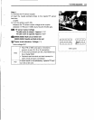
,ggt.
09900-25008:
Multi
circuit
tester
set
~
Tester
knob
indication:
Voltage
(=-::)
Is
the
voltage
OK?
YES
Go to
Step
2.
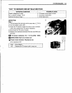
•
Loose
or
poor
contacts
on the
ECM
coupler.
NO
•
Open
or
short
circuit in the Red
wire
or
B/Br
wire.