


4-44
FI
SYSTEM
DIAGNOSIS
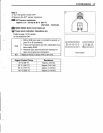
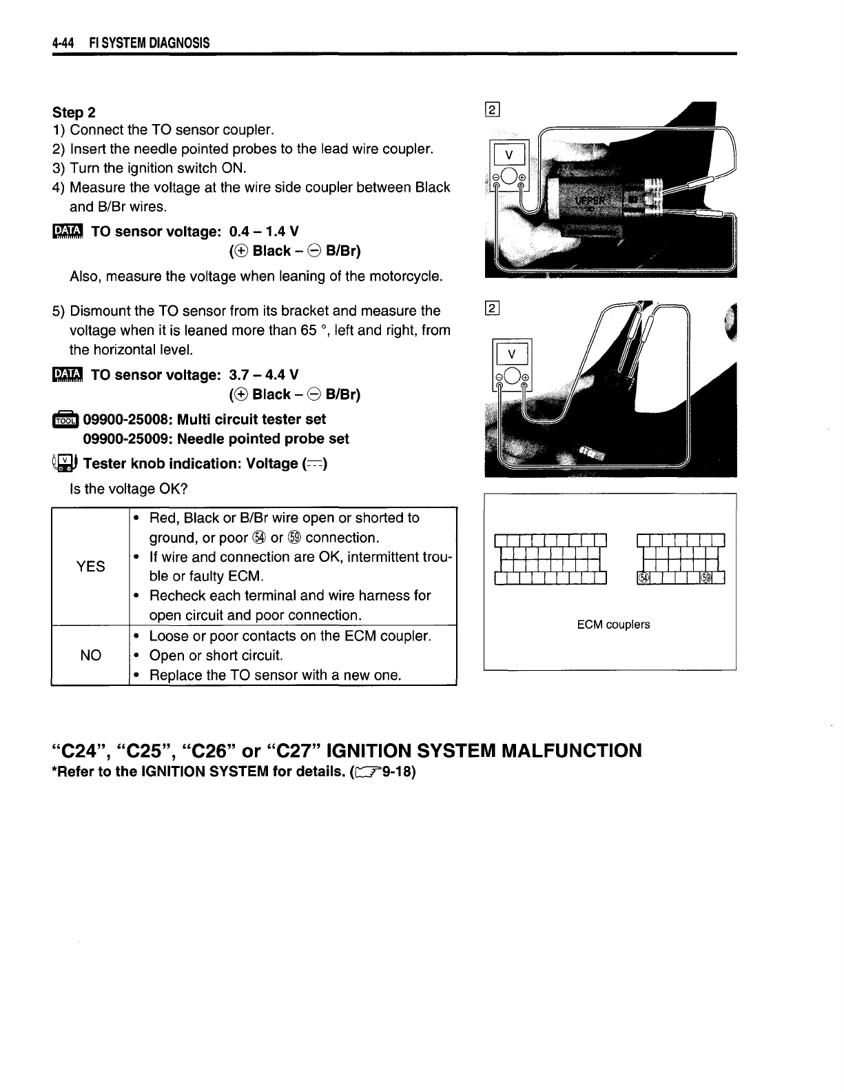
Step 2
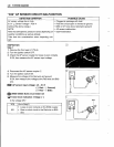
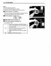
1) Connect the TO sensor coupler.
2) Insert the needle pointed probes to the lead wire coupler.
3) Turn the ignition switch ON.
4) Measure the voltage at the wire side coupler between Black
and BIBr wires.
_ TO
sensor
voltage: 0.4 - 1.4 V
(CB
Black - 8 B/Br)
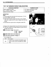
Also, measure the voltage when leaning of the motorcycle.
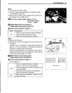
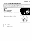
5) Dismount the TO sensor from its bracket and measure the
voltage when it is leaned more than 65
0,
left and right, from
the horizontal level.
_ TO
sensor
voltage: 3.7 - 4.4 V
(CB
Black - 8 B/Br)
,roOt,
09900-25008: Multi
circuit
tester set
09900-25009: Needle pointed probe set
~
Tester
knob
indication: Voltage
(=-:-:)
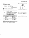
Is the voltage OK?
•
Red, Black or BIBr wire open or shorted to
ground, or poor
~
or
@l
connection.
•
If wire and connection are OK, intermittent trou-
YES
ble or faulty ECM.
•
Recheck each terminal and wire harness for
open circuit and poor connection.
•
Loose or poor contacts on the ECM coupler.
NO
• Open or short circuit.
•
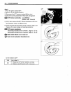
Replace the TO sensor with a new one.
ECM couplers
"C24",
"C25",
"C26"
or
"C27"
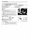
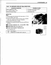
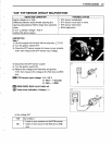
IGNITION SYSTEM MALFUNCTION
*Refer to
the
IGNITION SYSTEM
for
details.
(CT9-18)