


4-24
FI
SYSTEM
DIAGNOSIS
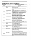
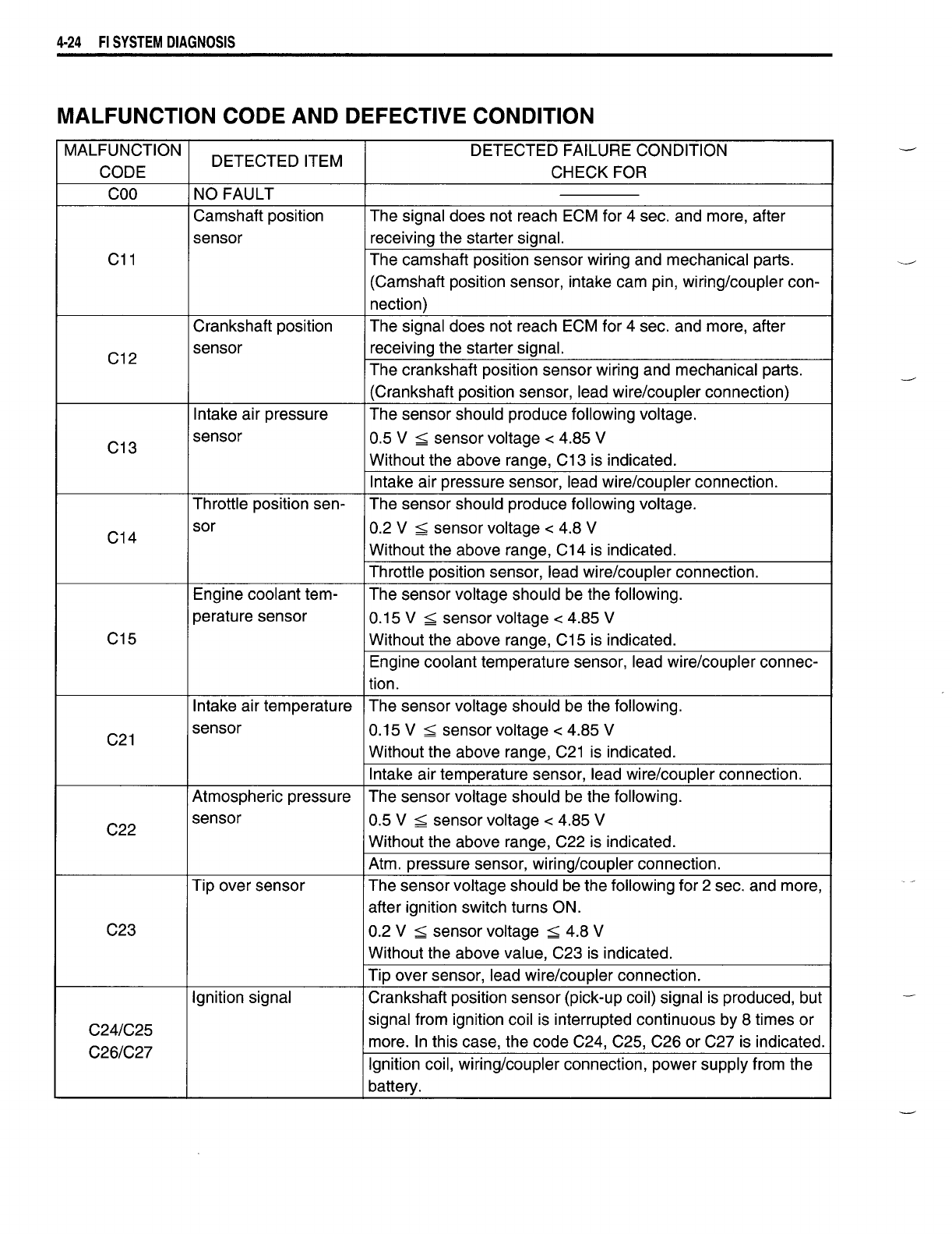
MALFUNCTION
CODe
AND DEFECTIVE CONDITION
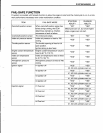
MALFUNCTION
DETECTED ITEM
DETECTED FAILURE CONDITION
CODE CHECK FOR
coo
NO FAULT
Camshaft position The signal does not reach ECM for 4 sec, and more, after
sensor receiving the starter signal.
C11 The camshaft position sensor wiring and mechanical parts.
(Camshaft position sensor, intake cam pin, wiring/coupler con-
nection)
Crankshaft position The signal does not reach ECM for 4 sec. and more, after
C12
sensor receiving the starter signal.
The crankshaft position sensor wiring and mechanical parts.
(Crankshaft position sensor, lead wire/coupler connection)
Intake air pressure The sensor should produce following voltage.
C13
sensor
0.5 V
;:;;;
sensor voltage < 4.85 V
Without the above range, C13 is indicated.
Intake air pressure sensor, lead wire/coupler connection.
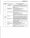
Throttle position sen-
The sensor should produce following voltage.
C14
sor
0.2 V
;:;;;
sensor voltage < 4.8 V
Without the above range, C14 is indicated.
Throttle position sensor, lead wire/coupler connection.
Engine coolant tem- The sensor voltage should be the following.
perature sensor
0.15 V
;:;;;
sensor voltage < 4.85 V
C15
Without the above range, C15 is indicated.
Engine coolant temperature sensor, lead wire/coupler connec-
tion.
Intake air temperature The sensor voltage should be the following.
C21
sensor
0.15 V
;:;;;
sensor voltage < 4.85 V
Without the above range, C21 is indicated.
Intake air temperature sensor, lead wire/coupler connection.
Atmospheric pressure The sensor voltage should be the following.
C22
sensor
0.5 V
;:;;;
sensor voltage < 4.85 V
Without the above range, C22 is indicated.
Atm. pressure sensor, wiring/coupler connection.
Tip over sensor The sensor voltage should be the following for 2 sec. and more,
after ignition switch turns ON.
C23
0.2 V
;:;;;
sensor voltage
;:;;;
4.8 V
Without the above value, C23 is indicated.
Tip over sensor, lead wire/coupler connection.
Ignition signal
Crankshaft position sensor (pick-up coil) signal is produced, but
C24/C25
signal from ignition coil is interrupted continuous by 8 times or
C26/C27
more. In this case, the code C24, C25, C26 or C27 is indicated.
Ignition coil, wiring/coupler connection, power supply from the
battery.