


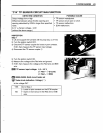
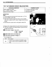
Step 2
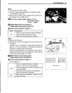
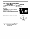
1) Connect the AP sensor coupler.
2) Insert the needle pointed probes to the lead wire coupler.
Turn the ignition switch ON.
3) Measure the AP sensor output voltage at the wire side cou-
pler (between GIY and B/Br wires).
_ AP sensor output voltage: Approx. 2.6 V at
760 mmHg (100 kPa)
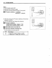
(@
GN
- 8
BIBr)
,roOt,
09900-25008: Multi circuit tester set
09900-25009: Needle pointed probe set
~
Tester knob indication: Voltage
(::-::-::)
YES Go to Step 3.
• Check the vacuum hose for crack or damage.
NO • Open or short circuit in the GIY wire.
•
Replace the AP sensor with a new one.
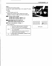
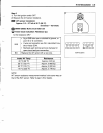
Step
3
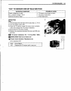
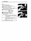
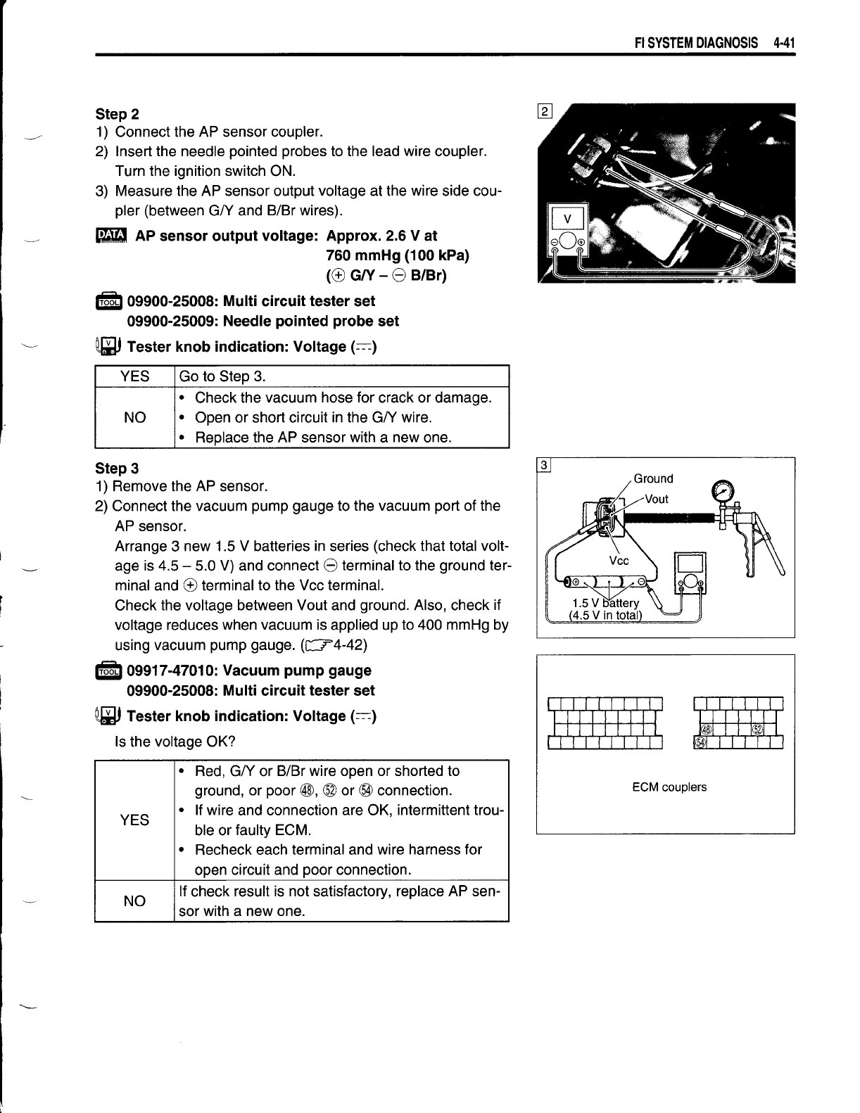
1) Remove the AP sensor.
2) Connect the vacuum pump gauge to the vacuum port of the
AP sensor.
Arrange 3 new 1.5 V batteries in series (check that total volt-
age is 4.5 - 5.0 V) and connect 8 terminal to the ground ter-
minal and @ terminal to the Vcc terminal.
Check the voltage between Vout and ground. Also, check if
voltage reduces when vacuum is applied up to 400 mmHg by
using vacuum pump gauge. (c:::::r4-42)
,roOt,
09917-47010: Vacuum pump gauge
09900-25008: Multi circuit tester set
~
Tester knob indication: Voltage
(::-::-::)
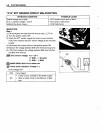
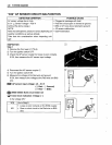
Is the voltage OK?
•
Red, GIY or B/Br wire open or shorted to
ground, or poor @, ® or
®l
connection.
•
If wire and connection are OK, intermittent trou-
YES
ble or faulty ECM.
•
Recheck each terminal and wire harness for
open circuit and poor connection.
NO
If check result is not satisfactory, replace AP sen-
sor with a new one.
FI
SYSTEM
DIAGNOSIS
4·41
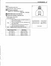
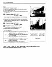
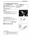
3
ECM couplers