


ELECTRICAL
SYSTEM
9·19
Step
2
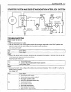
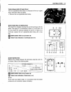
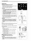
1) Measure the battery voltage between input lead wires at the ECM with the ignition switch in the "ON"
position. (E-02, 19: O/G and BIW, E-03, 24, 28, 33: OIW and BIW)
Is the voltage OK?
YES Go to Step 3.
•
Faulty ignition switch.
•
Faulty turn signal/side-stand relay.
NO
•
Faulty engine stop switch.
•
Broken wire harness or poor connection of related circuit couplers.
Step
3
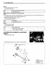
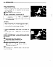
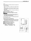
1) Measure the ignition coil primary peak voltage. (c:::79-20)
NOTE:
This inspection method is applicable only with the multi circuit tester
and
the
peak
volt adaptor.
Is the peak voltage OK?
NO Go to Step 5.
IYES IGo to Step 4.
Step
4
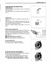
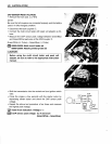
1) Inspect the spark plugs. (c:::72-6)
Is the spark plug OK?
IYES IGo to Step 5.
StepS
1) Inspect the ignition coil/plug caps. (c:::79-21)
Is the ignition coil/plug cap OK?
YES Go to Step 6.
•
Poor connection of the ignition coil/plug cap (-s).
NO
•
Faulty ignition coil/plug cap (-s).
Step
6
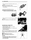
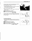
1) Measure the crankshaft position sensor peak voltage and its resistance. (c:::79-22, 23)
NOTE:
The crankshaft position sensor
peak
voltage inspection is applicable only with the multi circuit tester
and
peak
volt adaptor.
Is the peak voltage and resistance OK?
•
Faulty ECM.
YES
•
Poor connection of ignition couplers.
NO Faulty CKP sensor.