


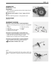
3-40 ENGINE
CLUTCH LIFTER PIN ADJUSTMENT
NOTE:
When adjusting the clutch lifter, it is not necessary to install the
clutch onto the countershaft.
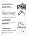
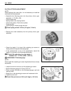
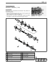
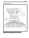
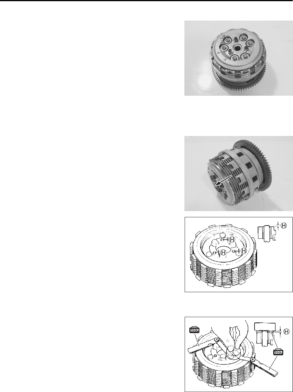
• Assemble the following parts into the primary driven gear
assembly. (3-85 to -88)
* Clutch sleeve hub
* Spring washer seat, Spring washer
* Clutch drive plates, Clutch driven plates
* Pressure plate
* Clutch springs, Clutch springs set bolts
Clutch spring set bolt: 10 N·m (1.0 kgf-m, 7.0 lb-ft)
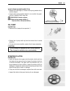
• Remove the clutch assembly from the primary driven gear
assembly.
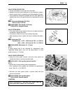
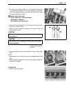
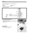
• Check the height H of clutch lifter adjusting pin screws at
three positions using the thickness gauge.
• If the measurement is out of the specification, adjust the
height H as shown in the following specification.
Clutch lifter adjusting pin screw height H
Standard: 0.2 – 0.4 mm (0.008 – 0.016 in)
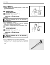
09900-20803: Thickness gauge
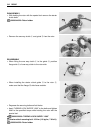
NOTE:
Each clutch lifter adjusting pin screw height should be as closely
as possible.
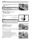
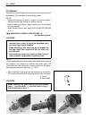
• Loosen the lock-nut and turn out the adjusting pin screw.
• Set the thickness gauge to 0.3 mm (0.012 in).
• Place a proper flat plate on the thickness gauges and hold
them by hand.
• Slowly turn in the adjusting pin screw until resistance is felt.
• Tighten the lock-nut.
Clutch lifter pin lock-nut: 23 N·m (2.3 kgf-m, 16.5 lb-ft)